As 5G Moves Towards 6G, Waveguides Will Supplement Connectors
Smaller and higher frequency assemblies add to the complexity of next-generation wireless equipment. Waveguides offer a powerful alternative to coax connectors.

Although 5G equipment is just beginning to roll out in production volume, the leading edge of wireless communications research and development and associated standards is looking towards 6G (sixth-generation wireless). The goal of 5G is sometimes summarized as “connected everything,” as it enables literally billions of devices to interact with each other. Although 5G is in its application infancy, we need to consider what may be involved with 6G, as new cellular technologies take more than a decade to go from concept to first deployment.
We do not know the final details of the equipment that will be needed to implement 6G, nor all the concepts involved, but 6G will extend this vision of connectivity to approach what prior generations might have called science fiction. Systems will operate faster, become ultra-reliable and smaller using shorter wavelengths, operate almost without latency, and be self-correcting. 6G will not start with all benefits, but some, such as integrated 3D area sensors, remote robotic surgery, and localized self-contained battle scenarios, are around the corner. The frequencies associated with 6G will use both coax and waveguide assemblies.
WiFi 6 and 6G
There is some confusion regarding 6G and WiFi 6. Wi-Fi is a lower cost local area network (LAN) used primarily indoors, such as in homes or offices. Cellular networks used by major operators, like the current 4G LTE networks and 5G and forthcoming 6G, are a wide area network (WAN) usually implemented for long distances or intensive local communications such as city-wide vehicle-to-everything (V2X). Both 5G with forthcoming 6G and Wi-Fi 6E (forthcoming WiFi 7 should be released by 2024) are complementary technologies that provide higher speeds, lower delay, and increased capacity over their predecessors. They use different technology and standards, with different frequencies and connectors. Wi-Fi 6 is based on the IEEE 802.11ax standard, while 6G protocols are established by an international industry consortium of standards organizations collectively known as 3GPP (3rd Generation Partnership Project).
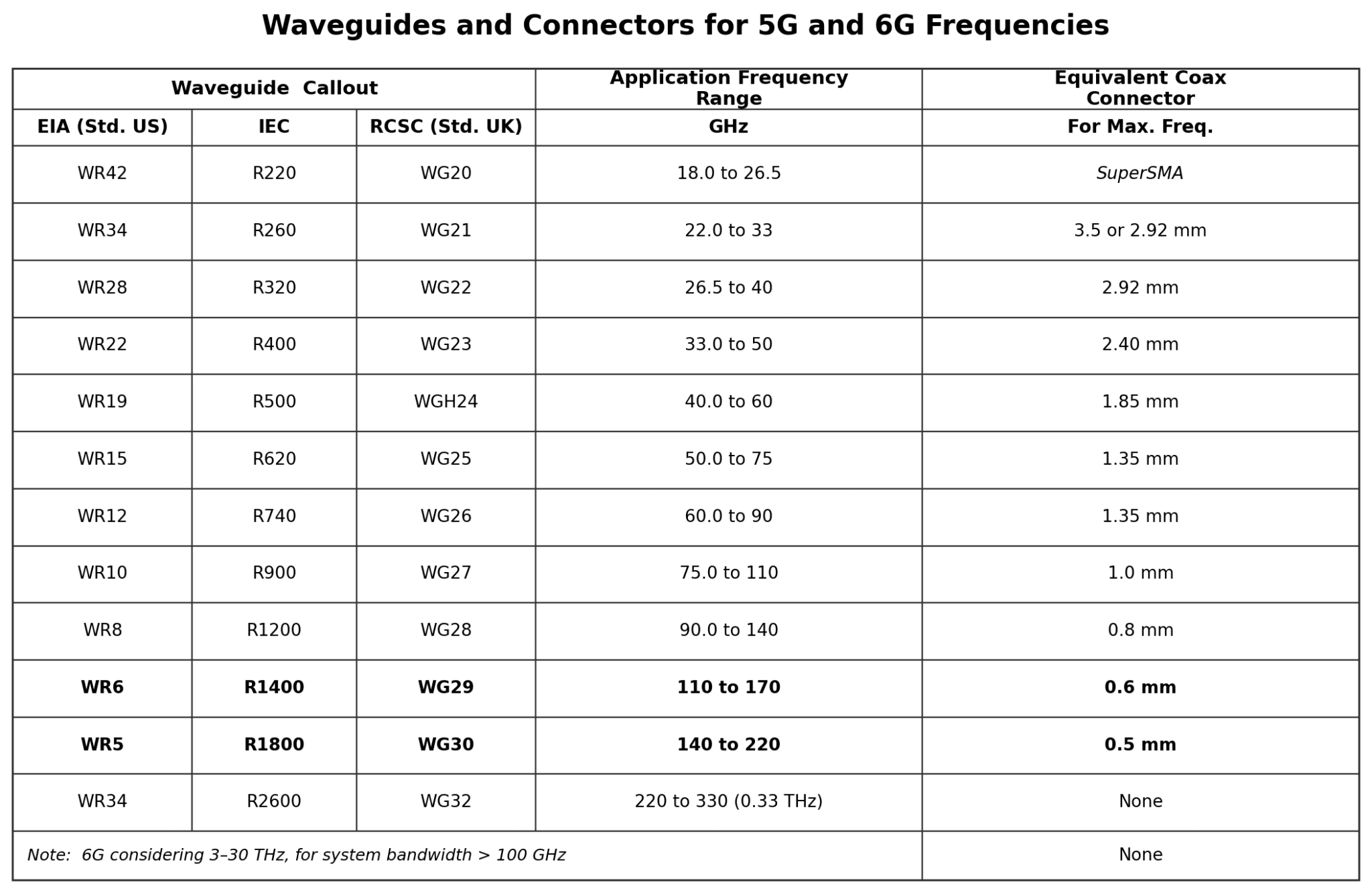
5G has assigned two frequency ranges: FR1 for up to 7.125 GHz and FR2 for 24.25 to 52.6 GHz. Most interconnect local service will be in the mid-band ranges (2.1 to 2.6 GHz and 3.3-3.8 GHz), while many 5G ultra-wideband networks will use 28 GHz and 39 GHz mmWave spectrum bands. 6G radio frequencies are being planned to work in the wavelength ranges above 95 GHz through low THz as this offers significant jumps in abilities to offer faster and denser data rates at frequencies often above the capabilities of today’s coax interconnect assemblies, but well within the performance of existing waveguides.
Waveguide Operation
Waveguides are hollow, rigid, reflective devices for transmitting energy. Optical, acoustic, and electromagnetic waveguides, and special versions, such as flexible and gas-filled waveguides, make this product suitable for a wide range of applications. An optical fiber is an example of a circular waveguide.
When size permits, waveguides often are preferred over coax assemblies as they conduct microwave energy at lower loss than coaxial cables and can operate at frequencies too high for coax cable. As fully enclosed components, waveguides also offer greater 360˚ shielding performance. Equivalents to coax cable assemblies with connectors at both ends are provided by waveguides with flanges for mounting. Connector-to-waveguide assemblies (physical transitions) can take advantage of the greater flexibility, lower costs, and multi-mating options offered by coax cables for at least portions of the assembly.
The size of the waveguide is directly proportional to the wavelength, and inversely related to the frequency. Waveguides work on the principle of “total internal reflection” and, for reflection to work, the wavelength of the frequency being transmitted needs to be smaller than the smallest dimension of the waveguide. Otherwise, the wave will diffract (spread out) and reduce transmission effectiveness. At low frequencies, this means that the waveguide dimensions must be very large. (Even at MHz frequencies, wavelengths are in kilometers.) Therefore, to have dimensions suitable for practical applications, most waveguides are used at microwave frequencies or higher with short millimeter wavelengths.
While coax connectors and cable assemblies are broadband, rated from DC to their maximum operating frequency, waveguides propagate signals within a specific range based upon their cutoff frequencies. The cut-off frequency is the frequency above which the waveguide offers minimum attenuation to signal propagation. Frequencies below the cut-off frequency are attenuated by the waveguide. The upper cutoff frequency is one octave above the lower (multiply the lower cutoff frequency by two). The operating range is the useful limits between the lower and upper cutoff frequencies; for rectangular waveguides this usually is between 125% and 189% of the lower cutoff frequency.
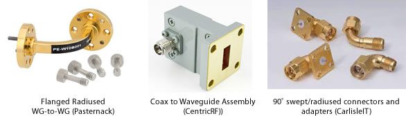
WG-WG Adapters and Assemblies
Waveguides offer different approaches for 90˚ (and other) bends. Coax-to-WG adapters require a flat section where the connector is mounted. Connector-to-connector adaptors may use swept/radiused or mitered/machined sections with performance dependent upon supplier capabilities.
Working with RF connectors and Waveguides requires that we understand how they are identified. Waveguides and many connectors are designated according to an inner diameter dimension. Precision coax connectors are identified by the ID of outer conductor (e.g., 2.40 mm, 1.85 mm, and 1.35mm connectors). Smaller diameters indicate higher frequency capabilities for both waveguides and coax connectors. The inner cross-section of most rectangular waveguides has a 2:1 aspect ratio (i.e., the broad wall is twice the dimension of the narrow wall). The “number” for a rectangular waveguide (WR) typically is the dimension of the inside broader (or “wider”) wall in thousandths of an inch divided by 10.
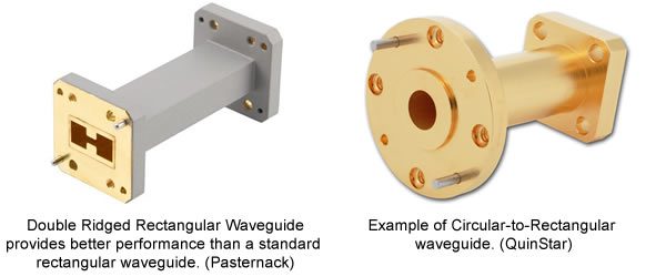
A designation of “WR” means a rectangular waveguide (“WC” is for Circular Waveguide) and the number with it indicates the dimension of the waveguide’s inner width in hundredths of an inch. There also are double-ridge waveguides which are rectangular waveguides with two ridges protruding parallel to the short wall, that provide better performance.
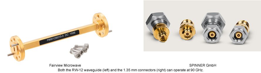
The 95 GHz for lower-end 6G corresponds to “E” Band frequencies, which historically used WR-12 waveguides as this was above the limit for coax connectors. Specifications for WR-12 waveguides include:
- Recommended Frequency Band: 60 to 90 GHz.
- Cutoff Frequency of Lowest Order Mode: 48.373 GHz.
- Cutoff Frequency of Upper Mode: 96.746 GHz.
- Dimensions: 0.122 Inches x 0.061 Inches (the 0.122” results in the “-12” identifier).
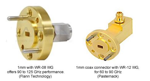
Coax connectors with rear probes (contact extensions) can be used to input RF energy into a WG assembly. The probe tip is located with preciseness in a waveguide to act as a quarter-wave antenna. Several coaxial connector-to-waveguide assemblies are presented below. The connector‘s maximum frequency must be within the range of the waveguide and, usually, determines the upper limiting frequency for the assembly. Results below include using a 1 mm connector with different WGs.
Connector and Waveguide Frequencies
As systems move upward in frequency, connectors also change. For newer RF hardware, SMAs are being replaced by 2.92 mm connectors for 40 GHz (plus enhanced versions for 44 GHz), while prior applications for 2.40 and V/1.85 mm connectors are being selectively superseded by 1.35 mm or 1 mm connectors for forward-designed communications and test equipment. Engineers at the Hughes Network Systems in Germantown, Maryland, are envisioning E Band for terabit per second (Tbit/s or Tb/s) terrestrial and satellite communications by the end of this decade. As 40 and 100 Gb/s Ethernet becomes the basis for high-speed internet backbone networks, Tb/s ratings will become common.
Some existing components, including chipsets, may work for those new applications, but higher power amplifier and antennas present challenges. Problems related to the mechanical hardware that will work at these frequencies are starting to be solved.
The higher frequencies used in 5G and (proposed) 6G will result in overlapping use of precision coax connectors, waveguides, and coax-to-connector adapters.
Waveguide Industry Standards
Just as coax connectors are covered by MIL-specs, EIA/IEC, ANSI, SAE, and other organizations, waveguides are standardized worldwide. Waveguide standards include:
- U.S. Military standard MIL-DTL-3922 is provides detailed descriptions of gaskets, covers, and flanges for rectangular waveguides.
- IEC (International Electrotechnical Commission) standard IEC 60154 describes flanges for square and circular waveguides.
- EIA (The Electronic Industries Alliance; previously called the Electronic Industries Association) currently defines the WR designations for standard rectangular waveguides. EIA flanges are designated CMR (connector, miniature, rectangular waveguide) or CPR (connector, pressurized). Typically, a rectangular waveguide is followed by the EIA number (WR number) for the relevant waveguide.
- RCSC (The Radio Components Standardization Committee) is the U.K. organization that originated the WG designations for standard rectangular waveguides.
Future Innovation
As 6G becomes closer to implementation, its existence will further expand communications and related technology into almost every aspect of life. The increased speed of business turnover will escalate productivity. The speeds and bandwidths involved will require systems with better signal-to-noise ratios as lower power will be used (with smaller components), which will be integrated over wider bandwidths. The move from mmWave to sub-THz frequencies will require continued development of new interconnect components. Anritsu now markets connectorized test equipment for 270 GHz using 0.6 mm connectors and has published papers discussing even higher frequency connectors. It is often said that everything electrical requires connectors, but this may need to be rephrased to include waveguides and connector-waveguide mixed assemblies.
Like this article? Check out our other RF and Coax, our Datacom Market Page, and our 2022 Article Archive.
Subscribe to our weekly e-newsletters, follow us on LinkedIn, Twitter, and Facebook, and check out our eBook archives for more applicable, expert-informed connectivity content.

- IMS2025 Brings New RF/Microwave Interconnects - July 22, 2025
- New Microwave and RF Advances Impress at IMS2024 - July 16, 2024
- New Circular Connectors Add to Multi-Billion Dollar Market - January 9, 2024