What are DIN 41612 Connectors?
Meet the Connector: DIN 41612 Connectors
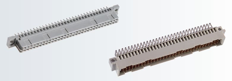
DIN 41612, a standard for electrical connectors used in rack-based electrical systems, defines 13 different types of connectors. DIN 41612/IEC 60603-2 connectors are used to establish a connection between the plug-in card and backplane, mainly for 19-inch racks. The wide variety of connector types combined with the high level of reliability enable flexible use of the DIN 41612 connectors in various connections, such as:
- plug-in card and backplane
- vertically stacked circuit boards
- horizontally stacked circuit boards
- over long distances using ribbon cable
- for signal transmission up to 1.5 A
- for power transmission up to 5.6 A or 15 A
ept THTR connectors, a high temperature DIN 41612 connector series made from temperature-resistant plastic, fulfills the requirements of J-STD-020D. ept showcased its first line of DIN 41612 connectors in 1980 and now offers options in DIN 41612 that include pre-mating and late-mating contacts (used for safety reason or hot swap functionality), right-angle as well as parallel connections, signal connectors up to 1.5A (Types B, C, M, Q, and R), power connectors up to 5.6 A (types D, E, F, and G), power connectors up to 15 A (H11, H15, H7/F24), special types and DIN 41612 accessories (VME 64x, shrouds, switching connectors, IDC types B and C).
DIN 41612 was first standardized in the 1970s. More recent international standards, IEC 60603-2, published in 1995, and EN 60603-2, the European equivalent, have largely replaced it. However, DIN 41612 is still regarded as a relevant standard in many areas, particularly industrial automation and rack-based applications.
DIN 41612 connectors are widely used in VMEbus and NuBus systems, for example, where components from different suppliers need to operate together. Other systems that use DIN 41612 are Pancon, STEbus, Futurebus, Multibus II, Acorn Archimded expansion bus, VXI bus, Eurocard TRAM motherboards, and European Card Bus. These systems generally use male DIN 41612 connectors on Eurocards and female DIN 41612 plugs on the backplane in 19-inch rack chassis.

Adam Tech DIN connectors feature a multitude of body sizes and styles with options that include selective contact loading, make and break contacts, contact lead length choices, and contact plating variations each in .100″ (2.54 mm) or .200″ (5.08 mm) centerline spacing.
Different connector configurations, such as pre- and late-mating contacts, make it possible to support the special functions of an assembly. The connecting contacts can be implemented as press-fit connection, as a soldering connection for wave soldering or reflow technology (THTR or Pin-in-Paste).
Coding special types prevents mismating types. DIN 41612 connectors in soldering technology are also offered with mounting clips known as board locks. Board locks make it possible to efficiently mount the connectors on the circuit board to enable safe soldering and significantly improve strain relief of the connector during the mating/unmating process.
Design Notes
Mating cycles:
500 mating cycles (class 1)
400 mating cycles (class 2)
50 mating cycles (class 3)
DIN 41612 connector systems from Amphenol Communications Solutions meet IEC 60603-2 specifications.
Contacts:
The standard describes connectors which may have one, two, or three rows of contacts, which are labelled as rows a, b, and c. Two-row connectors may use rows a+b or rows a+c. The connectors may have 16 or 32 columns, which means that the possible permutations allow 16, 32, 48, 64, or 96 contacts. The rows and columns are on a 0.1” (2.54 mm) grid pitch. Insertion and removal force are controlled, and three durability grades are available.
Often the female DIN 41612 connectors have press-fit contacts rather than solder-pin contacts, to avoid thermal shock to the backplane.
Pins and pin numbering:
Normal versions have right-angle PCB mounting pins on the DIN 41612 connector and straight PCN mounting pins on the DIN 41612 plug, but reversed connectors (straight mounting pins on the connector and right-angle mounting pins on the plug) also exist. The row ordering and pin numbering remains the same, even if a normal version is replaced with a reversed version: male pin 1 becomes female pin 1. If two boards are designed to connect edge-to-edge with no backplane, one board requires a male connector with right-angle pins (normal) and the other requires a female connector with right-angle pins (reversed). The row ordering is unchanged but the pin ordering is mirrored: male pin a1 is connected to female receptacle a32.
Termination methods: solder, crimp, press-fit, wire wrap, insulation displacement connection (IDC), and clamp
Electrical properties (with allowable safety requirements and environmental conditions):
2 A per pin current carrying capacity
500 V working voltage
Markets
Industrial, Telecom, Medical, Military and Aerospace, Transportation
Applications
Manufacturing, industrial automation, control devices; telecommunications; medical devices; press-fit technology, computer backplanes, rack-based computer systems; Test & Measurement, instrumentation; military equipment.
Suppliers
Adam Tech, Amphenol Communications Solutions, Cinch Connectivity Solutions, ept, HARTING, Hirose Electric
Related products
Like this article? Check out our other Meet the Connector and Connector Basics articles, our Military and Aerospace Market Page, and our 2024 and 2025 Article Archives.
Subscribe to our weekly e-newsletters, follow us on LinkedIn, Twitter, and Facebook, and check out our eBook archives for more applicable, expert-informed connectivity content.
- What is a PBOF Interconnect? - July 14, 2026
- IP-Rated Interconnects Product Roundup - July 14, 2026
- July 2026 New Connectivity Products - July 14, 2026