Nine Considerations for Building a High-Reliability Cable Assembly
High-reliability applications demand robust, reliable, and long-lasting cable assemblies. These nine key considerations will help guide engineers as they select and secure cables for these designs.
Designing a robust cable assembly or wire harness that can support high-reliability connector performance, withstand the rigors of rugged operating environments, and streamline wiring designs to fit the needs of product geometries depends on strategic system design and careful cable selection. Ease of installation is another important part of cable assembly design. Many considerations go into selecting a cable type and installation method.

In many cases, the connectors specified for a design are pre-defined based on size, type, configuration, and application requirements. Selecting an appropriate cable depends on the type of signals or power the cables will carry, the application and operating environment it will be used in, and the cable routing requirements. In some applications, such as RF, data communications, or products like thermocouples, standards define the cable that must be used. This makes the decision-making process easier. However, for many applications, a variety of criteria must be evaluated in order to make the right choice.
Cable Type
Specific cable types serve specific applications. For example, coaxial cable is used for RF applications, ribbon cable is used for insulation displacement contact (IDC) connectors, shielded cable is required for noise-sensitive applications, and simple equipment wires economically serve many basic applications. If some or all of the cable needs to transmit power, the conductor wires must be sized appropriately to ensure that they can handle the current and that the voltage drop along the cable length is acceptable in all operating conditions. Once a basic cable type is determined, specific variations within that type can be considered.

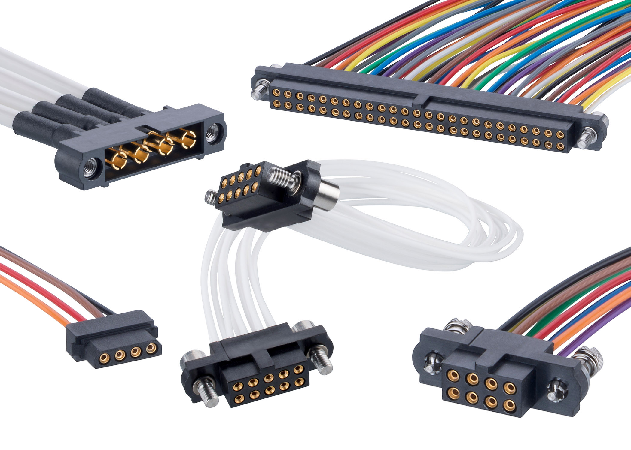
Harwin’s Datamate coax cable assemblies deliver power and data to high-reliability applications.
Solid Core or Stranded
If the application is exposed to outdoor or other harsh environment conditions, or if limiting cost is a significant concern, then solid core cable can be a good option, as it is more resistant to damage and generally easier to install, which makes it more economical as well. However, solid core cables can also be harder to crimp and are less flexible and more resistant to reshaping than an equivalent stranded cable. In smaller applications, multi-strand cable is often preferred.
Shielding
In two-way cabling environments and noise-sensitive applications that operate in areas with multiple electronic devices, cable assembly shielding is typically needed. In some applications, shielding may be required to protect high-impedance signals in the cable from interference as they pass noisy areas of the system. Conversely, if a cable assembly is carrying high-speed digital signals, then shielding can protect sensitive areas of the system that the cable passes through. Taking this one step further, cable shields can cover all conductors as a group, as pairs, or individually. If a cable carries both analog and digital signals, shielding one core from another prevents crosstalk.

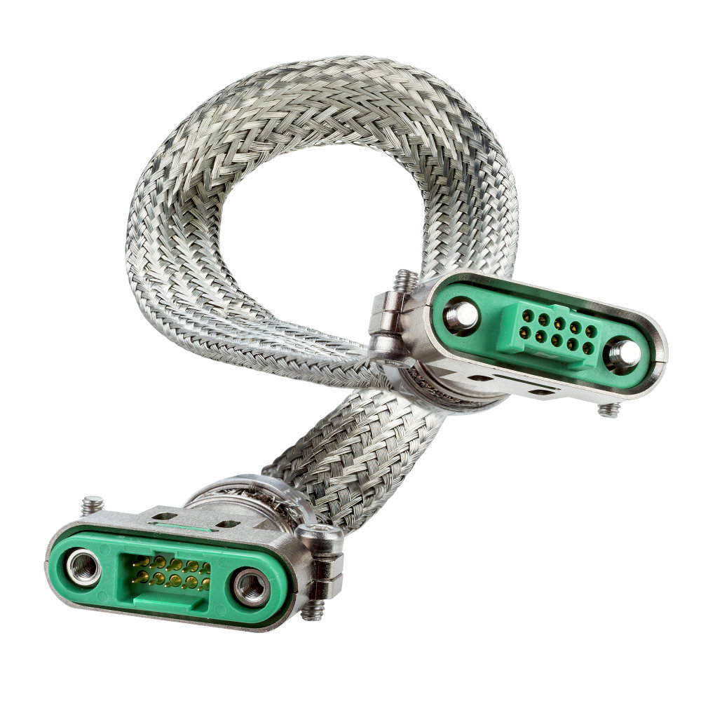
A shielded cable assembly equipped with Harwin’s male and female Gecko-SL connectors. High-reliability twisted and shielded cable assemblies like these prevent interference by fully covering the cables in metal braid. Both ends of the braid are terminated on metal backshells for complete covering.
Insulation
Cable routing is a key criterion for selecting insulation. If the outer sheath of the cable be exposed to extreme temperatures, chemicals, or potential for physical damage, such as abrasion, rugged insulation materials made to resist damage or degradation are required. Insulation damage can expose conductors, impair functionality, and create a serious safety hazard. Insulation type also helps determine the minimum bend radius for the cable, which is another important parameter for cable routing, especially in restricted locations. In addition to the insulation jacket that protects the cable or cable bundles, design engineers must also consider the insulation on individual cores, especially with regard to the dielectric strength that prevents any electrical breakdown.
Strain Relief
The application and operating environment can impact some of the finishing operations that form part of the overall design. For example, some shell-type connectors include an inset that can be filled with an epoxy resin after assembly. This process, known as backpotting, provides a degree of strain relief on the cable assembly and also protects against dust ingress, which can be a source of premature failure. With connector types that don’t have a backpotting void, the simple application of heatshrink can group individual cables and provide strain relief. Heat-shrink materials can also be applied over the outer sheathing of cables to provide increased rigidity and protection against wear mechanisms, such as abrasion.
Adding backshells to connector assemblies is another effective strain relief method. In connector systems that have a provision for this addition, backshells provide significant mechanical strength, as well as somewhere to grip the connector when mating and unmating. Backshells are widely available in plastic and metal versions for broad application suitability. Metal versions used with shielded cables offer a means of termination for the braided shielding, ensuring that the connector itself is also shielded, while plastic backshells are ideal for weight-critical applications.
Routing
In some cable runs, forming the cable so that it avoids sensitive parts of the system or makes strategic use of available space helps create a more effective cable assembly. In systems with movement or vibration, cable assemblies have to be routed close to the chassis for attachment proximity and physical support. Cable management products can secure looms to the chassis or PCBs. In high-vibration applications, further anti-wear measures, such as cable clips should be considered as part of the complete harness installation.
Twisted Pairs
Twisting two or more cables within the cable bundle, most typically in pairs, reduces electromagnetic radiation and crosstalk between neighboring pairs of lines. The twist will have a specific pitch, usually defined in TPI, or twists per inch.

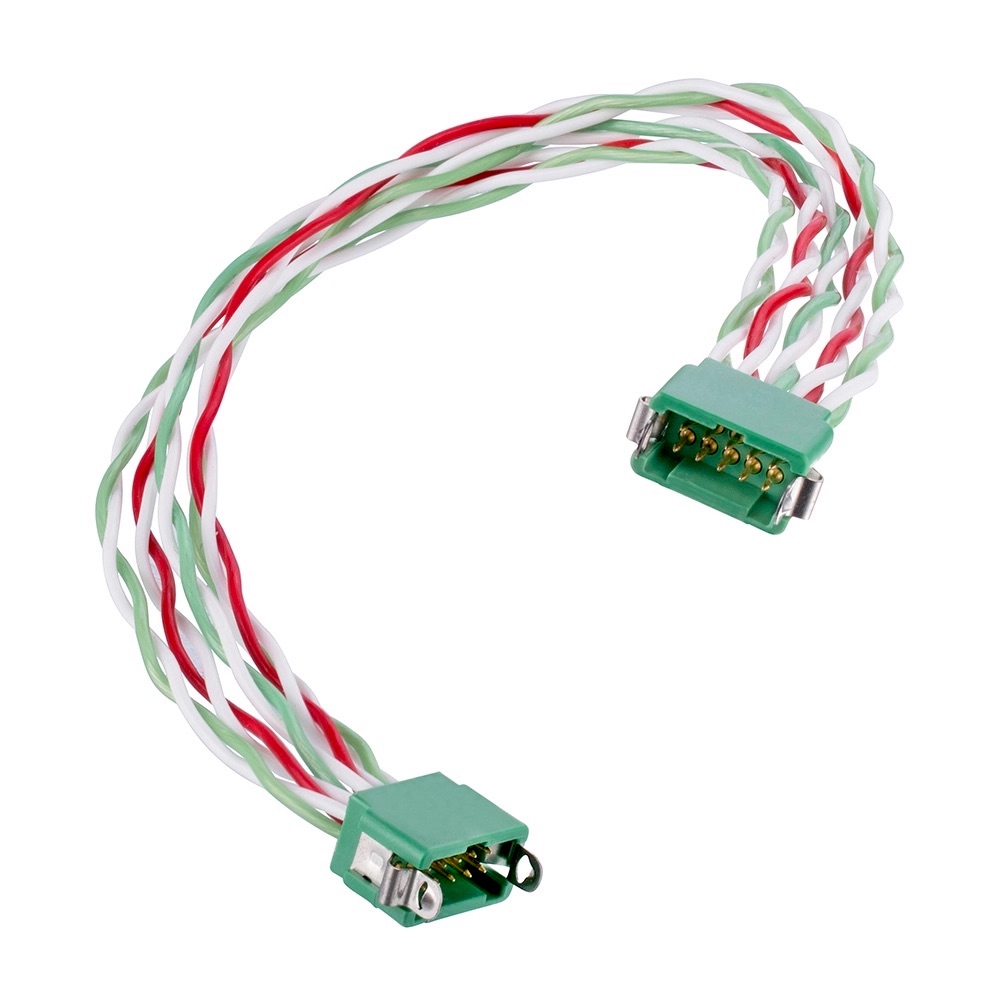
A 28AWG double-ended, twisted-pair cable assembly equipped with Harwin’s male 13+13-position, 1.25mm-pitch Gecko Latch connectors. Using twisted pairs in the assembly reduces electromagnetic radiation from wire pairs.
Lacing and Cable Ties
Cable ties are the most common and cheapest form of cable management. Cable lacing is an older type of cable management for binding cable bundles. The lacing forms a single cable assembly without any obstructions along the length, unlike plastic or hook and loop cable ties, which makes it a valid choice in tight spaces. This approach is very effective in applications subject to vibration-induced wear and tear.
Identification
The final consideration is whether any cable markings or special identification are required. This can be in context of the overall assembly, so that spares can be ordered, or for individual wires to identify routing of important signals. If a cable assembly is intended to be a service item in the field, assembly marking should be deemed essential to better assist service technicians.
Completing the Cable Assembly
Once all these aspects have been considered, the outcome should be a drawing package for the final cable assembly that includes a schematic, a mechanical outline, and a complete bill of materials that lists all of its components, including wire, connectors, and accessories. This drawing package will provide designers with a good understanding of the manufacturing processes and any tooling or jigs that will be required to build the final cable assembly.
Like this article? Check out our other How-to-Specify and Connection Basics articles, our Wire & Cable Assemblies Market Page, or our 2021 and 2020 article archives.
- How to Source Connectors and Cabling for Industrial Applications - February 8, 2022
- Nine Considerations for Building a High-Reliability Cable Assembly - February 16, 2021


