Robotic Soldering Process Optimization: Spattering and Solder Spread
Growing interest in robotic soldering within the PCB assembly industry is leading to increased demand for robotic soldering equipment and applications. Learn how this soldering technique can bring production, performance, and cost benefits.
Robotic soldering is emerging as a powerful PCB assembly tool. Not only is this method more efficient than hand soldering but it aids in alleviating human error. The robotic soldering process is more controlled and repeatable than a selective soldering fountain and can increase productivity and profitability. To help engineers understand this process, we’ll examine the effect of cored wires with different flux percentages on robotic soldering performance. All wires used in this project were SAC305 alloy with a 0.020” diameter and 3%, 3.5%, 4%, or 4.5% flux.
Adoption Drivers
The evolution of manufacturing and production processes has led electronics assemblers and assemblers in other industries to adopt robotic soldering. In manufacturing, what started as physical work moved to mechanical work, and later progressed to assembly line work. The rise of computer-assisted work has gradually led to the availability of programmable, fully automated processes. Robotic soldering machines first appeared in the early 1980s and have advanced into the efficient and reliable equipment we use today.
There are multiple reasons to adopt an automated soldering system into the PCB assembly process. First is the consistently accurate and repeatable application of solder to the desired joint. The robot, once programmed, will apply the same amount of solder and heat to the desired solder joint location for the same amount of time, every time. Increased repeatability allows for reductions in manufacturing costs such as those associated with personnel and the amount of rework needed.
Additionally, the industry is seeing a natural exodus of skilled hand soldering experts. This deficiency in skilled operators presents assemblers with two options: costly training of new operators or investment in an automated soldering system.
Benefits of Automated Soldering
Versatility and efficiency are the chief advantages of employing robotic soldering in the assembly process. Increased consistency and reliability reduce the need for reworking a board, saving users time and labor costs. Once fully optimized, the equipment purchaser will see a measurable return on investment via improved throughput.
Applications
Assemblers might consider robotic soldering where it is unreliable or impossible to employ mass soldering (wave soldering or solder paste) and where human soldering is too costly or unreliable. Robotic soldering is also appropriate when the component being assembled is heat sensitive and requires that only the joint area, not the entire component, be exposed to heat. Another possible application is when a large component is added that would make the mass reflow profile too difficult or too slow.
Applications where robotic soldering would not be ideal are those where it is too costly or time consuming to solder each joint individually. For instance, mass soldering techniques, such as wave soldering, can bond many joints more quickly. Additionally, situations where a human decision is required may not be the best fit for robotic soldering.
The Role of Flux-Cored Solder Wire
What do robotic soldering equipment suppliers look for in cored wire?
Throughout our experiment, there was extensive discussion regarding the features that would deliver an efficient robotic soldering experience. To summarize that discussion, three primary attributes were found to be desired by robotic soldering equipment manufacturers and their customers.
First, the solder feeds well into the machine and the solder joint. From a solder supplier’s perspective, this means that the solder wire should be evenly wound to prevent kinks in the machine. Enough tension must be placed on the wire as it leaves the spool and enters the machine’s feeding mechanism to help prevent kinking or too much slack in the wire, both of which can cause the wire to break if pulled with enough force. Feeding well also means that the wire should be void-free, meaning that there should not be any gaps in the wire containing an empty core. Voids in the wire will likely result in poor wetting and subsequent downtime.
Second, the solder flows well. This will pre-tin the iron fully and then, once applied at the joint, will flow effortlessly to create the desired joint. Achieving effortless flow will require fine-tuning of factors, such as wire diameter, flux formula, flux percentage, tip temperature, and dwell time.
Third, the solder wire does not damage the soldering iron tips. The soldering iron is one of the most important pieces of the robotic soldering machine and process. The soldering iron must be able to repeatedly provide a consistent supply of heat to the solder joint. The ingredients in a core flux formula can have dramatic effects on the speed of degradation of a soldering iron. The correct type and size of tip used based on the application to fully optimize the soldering process is also vital.
What do soldering equipment users look for in cored wire?
Once installed, the soldering wire will likely be determined either by the in-house engineering team or by a recommendation from the equipment supplier. In either instance, the solder wire characteristics listed by the equipment supplier also apply for the customer. Solder that feeds well and flows well allows for consistency and accuracy while improving the overall cycle time of completing the board. This reduces the need for rework. Soldering iron tip degradation needs to be taken into consideration when determining what flux formula to use. Excessive need for re-installing soldering iron tips reduces the overall cycle time, as well as increases the overall cost of assembly.
An attribute not mentioned previously concerns the cosmetics of the board post-soldering, as some flux formulas are prone to spatter more than others. This has become such an important characteristic for this part of the electronics assembly industry that solder wire suppliers are now releasing “low-spatter” formulas to improve post-soldering cleanliness and aesthetics (Figure 1).
Spatter Matters
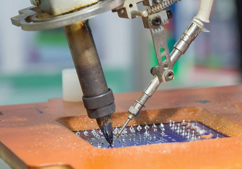
Spatter refers to the explosive spray of materials (flux and possibly solder) that “spit out” from the wire after heat has been applied. It is often caused by the out-gassing of the flux during the soldering process. Cosmetically unappealing spatter can increase cleanup time, potentially harm human operators, and have a negative impact on a robotic soldering machine’s visual inspection system.
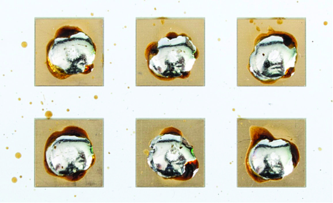
Figure 1. Excellent spattering performance (3%).
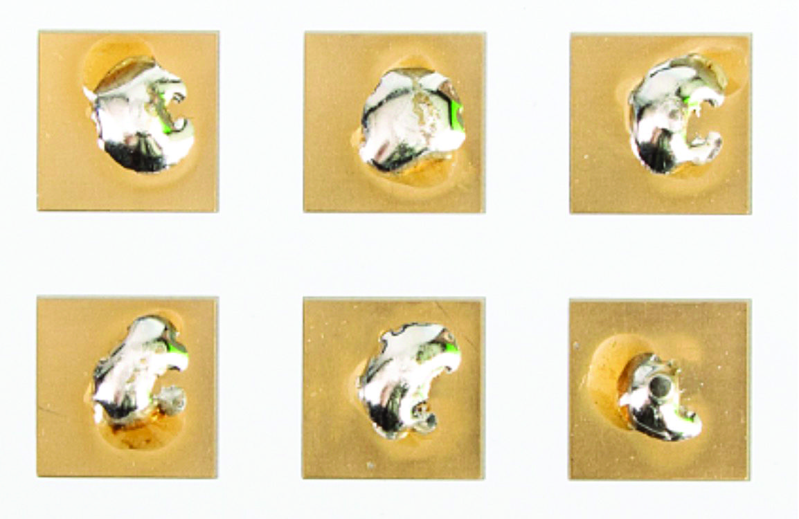
Figure 2. Poor spattering performance (3%).
Formula Influences Spattering More than Flux Percentage
In a robotic soldering assembly process, formation of the solder joint does not involve direct human interaction. Therefore, the assembler will typically want to use as much flux as possible to ensure that wetting occurs and the ensuing solder joint is adequate. When the flux percentage was increased from 3% incrementally to 4.5% using the same core flux formula, some improvements were shown in the rate of wetting and the spread of the solder. While this may be attractive when considering cycle times and overall production output, another factor that should be considered is spatter. Our study found that spattering is influenced by formula more than flux percentage. As seen in our formula control group, the spattering performance of each board is relatively similar using flux percentages ranging from 3-4.5% (Figure 3).
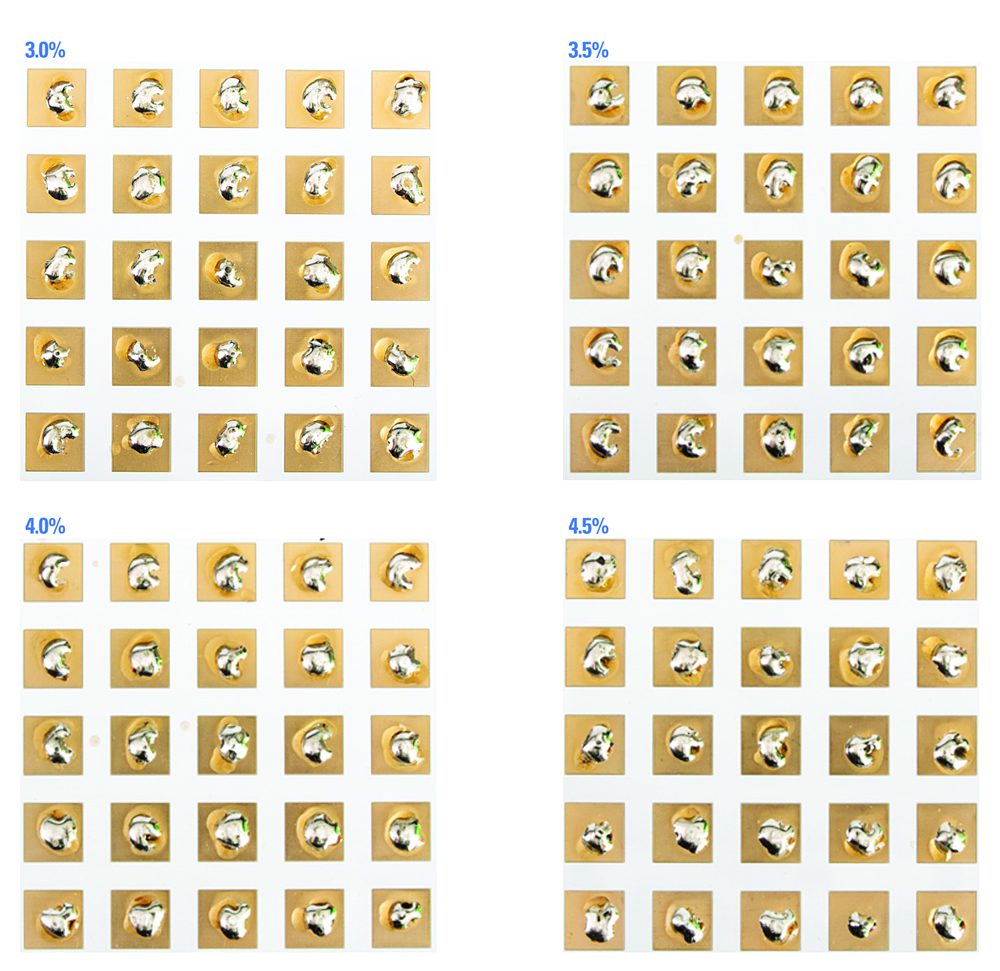
Figure 3. Control group.
The results showed that not all flux percentages and activity levels were created equal. As was expected, the activity level of the flux at 3% of the core improved congruently with the appearance of spread and wettability, meaning that testing done with J-STD-004A ROL0 did not perform as well as J-STD-004A ROL1, and both performed inferior to J-STD-004A ROM1. However, in regard to spattering, it should be noted that as the activity level went from “L” to “M,” there was a tendency for decreased spattering performance, as shown in Figure 4.
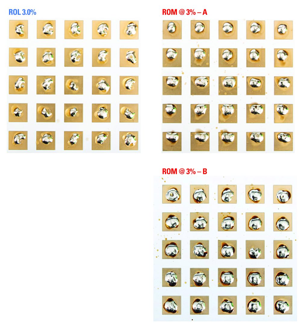
Figure 4. Decreased spattering performance.
To learn more about advanced soldering processes and materials, visit Indium Corporation.
Contributed by Indium Corporation
- Inside Device Connectivity: The Hidden Enabler of Software‑Defined Vehicles - July 14, 2026
- Bringing Modularity to Multi‑Board Systems - June 30, 2026
- Engineering’s Future is AI-Inspired, Human-Led - June 23, 2026