Three Things to Consider When You Have a Need for Data Speed
Copper cable beats wireless connectivity for high-speed applications, and fiber optics beats copper for the amount of data that can travel quickly. Consider connector and cable design options and test carefully to select the right components for your high-speed application.
We continue to find new ways to push more and more high-speed data through our connectivity solutions to satisfy the needs of applications that rely on constant streams of accurate data. This means leveraging solutions such as USB 3.0, 10Gb/s Cat 5e, HDMI, and a veritable alphabet soup of other data transmission protocols to support next-generation technologies including the Internet of Things and AI. Everything and everyone will soon be connected. With the rise of Industry 4.0, wearables, and new technologies in the defense and medical industries, today’s engineers are not only challenged to get all the necessary data transferred but to figure out how fast we can get the massive amounts of data to move as well. Wired connections still transport more data faster than wireless, so the hunt for faster data speeds without interference continues to drive innovation in connectors, traditional copper cabling, and fiber optics.

1) Connector Design and Selection
Designing a connectivity solution for a specific data protocol requires optimizing the design of both the connector and the cable. While they have to work properly together, the first condition for a functional solution is to have a connector that is capable of handling a specific protocol or multiple high-speed protocols. The protocol or protocols used will determine the number of contacts for each connector.
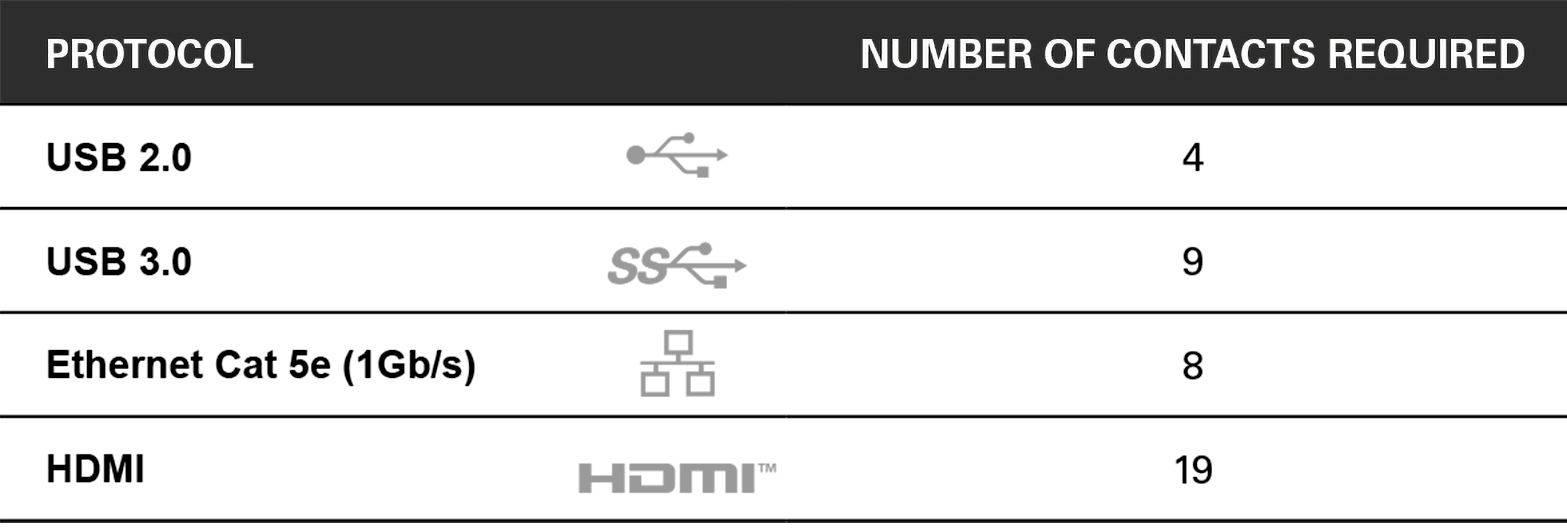
Each protocol requires specific design rules for the connector. For instance, the Fischer MiniMax Series of connectors has a specific connector configuration that delivers USB 3.0 speeds. It was designed using materials that help reduce interference and employs a unique nine-pin configuration to reduce the size of the physical connector while still delivering the data speed demanded by military, medical, and industrial companies. Technically, you could run Ethernet on this connector because Ethernet requires fewer contacts than USB 3.0, but there are other contact configurations available that are especially designed to maximize Ethernet data speeds.
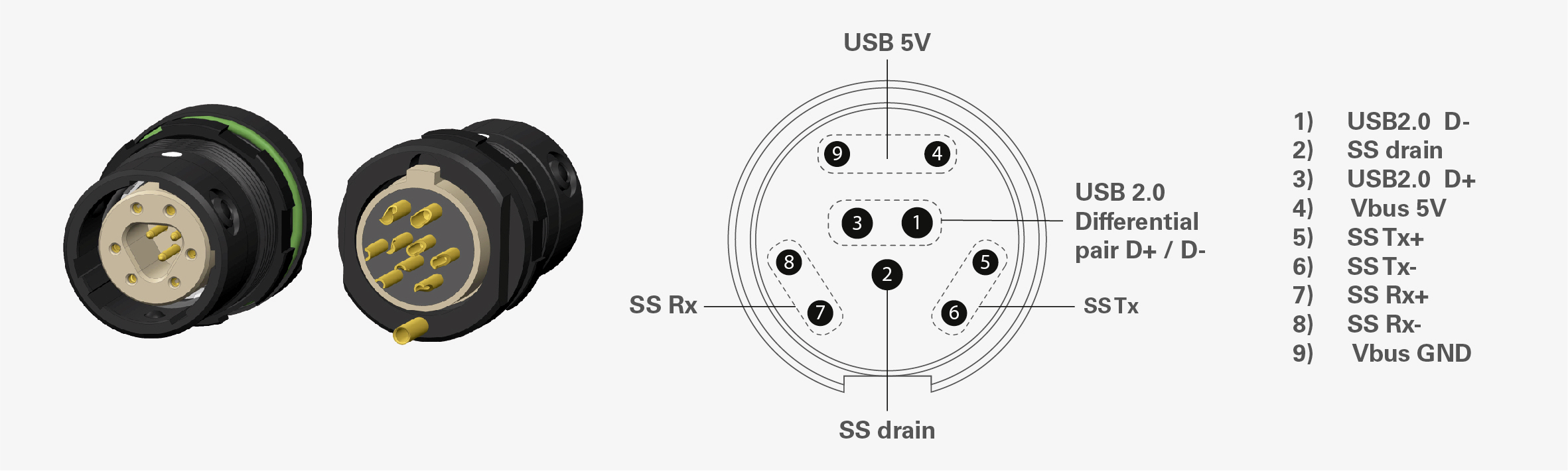
The Fischer MiniMax Series with nine contacts is an example of a connector that has been specifically designed to achieve high-speed data transfer using a single protocol (USB 3.0).
Multi-protocol connectors are still capable of high speeds. They just combine all of the relevant protocol-specific design rules within a single connector.
2) Cable Design and Selection
You have to look beyond the connector and its configuration to achieve a certain data speed. The construction of the cable itself plays a huge role in determining whether a connectivity solution will meet high-speed data requirements.
International standard ISO/IEC 11801 specifies general-purpose telecommunication cabling systems (e.g., structured cabling) that are suitable for a wide range of applications including analog and ISDN telephony, various data communication standards, building control systems, and factory automation. Balanced cabling performance is defined by a set of multiple parameters. The most relevant are insertion loss (IL), return loss (RL), near-end crosstalk (NEXT), and far-end crosstalk (FEXT).
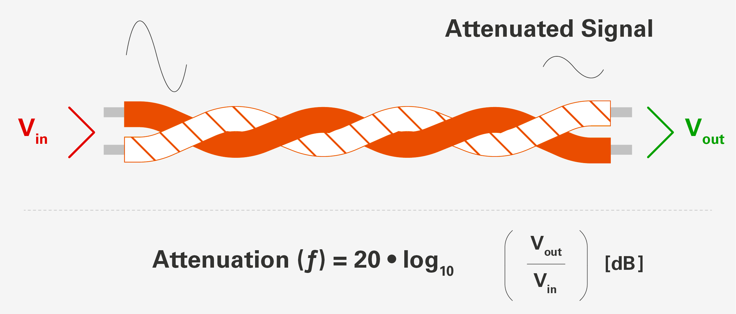
Insertion loss, or attenuation, is the reduction in amplitude of a transmitted signal in a wire pair as a function of the frequency.
In ISO/IEC standards, structured cabling components (e.g., cables, connecting hardware, and patch cords) are characterized by a performance category, and are mated to form a permanent link or channel that is described by a performance class. In TIA Standards, components and cabling are both characterized by a performance category.
Cable Categories
ISO/IEC 11801 defines the following correspondences between component category and balanced cabling performance class:
- Category 5 components provide Class D balanced cabling performance
- Category 6 components provide Class E balanced cabling performance
- Category 6A components provide Class EA balanced cabling performance
- Category 7 components provide Class F balanced cabling performance
- Category 7A components provide Class FA balanced cabling performance
ISO/IEC 11801 defines both the performance values that have to be achieved within the frequency range for each class and the balanced cabling class recommended for various types of applications. For example, you need Category 5 (Cat 5) components to produce a Class D balanced cabling that can be used for Ethernet 1000Base-T applications (i.e., Gigabit Ethernet per IEEE 802.3ab). The USB 2.0 protocol is less severe and only requires a minimum insertion loss value up to 400MHz. Other common parameters, such as return loss, near-end crosstalk, and far-end crosstalk, are not specified in the USB 2.0 specification.
Cable Shielding
Shielding also plays a role in data speed. ISO/IEC 11801:2002 aims to create an international standard for the designations of shielded cables: U for unshielded, S for braided shielding (outer layer only), and F for foiled shielding. These designations indicate the type of screen or shield for overall cable protection and the protection of twisted pairs (TP) or individually shielded twisted pairs in quads (TQ) and will help in cable selection.
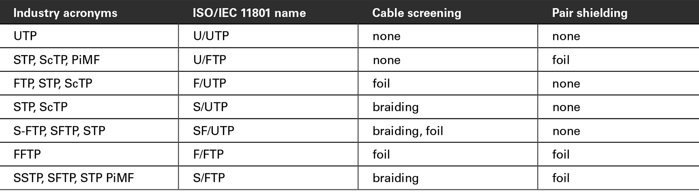
Examples of ISO/IEC 11801:2002 shielded cable designations. The code before the slash designates the shielding for the cable itself, while the code after the slash determines the shielding for the individual pairs.
Fischer Connectors’ director of engineering in the U.S., David Cianciolo, has become an expert in the design and selection of cables to achieve the speed required for a specific application. He says when it is critical that your rugged interconnect solution achieves a certain speed such as USB 3.0, you have to test the connector and cable together. Most connector suppliers will have specific cable recommendations that will save you the trial and error of testing connectors and cables together.
3) Simulation and Testing
Once a connector and cable have been designed and optimized for a defined protocol, a physical product prototype needs to be tested to validate the full characterization using a network analyzer. It’s not outside the realm of possibility for a connector and a cable to each separately pass a speed test but then fail when put together, so it’s crucial to test the full assembly.
Physical testing for multiple connectors and cables can become cumbersome, so many companies turn to simulation software to find the best fit. Simulation software is the perfect tool for this design process since it allows designers to verify the compatibility of the complete cable assembly with the targeted protocol. It also allows the effects of design modifications to be immediately evaluated in time and in the frequency domain, which enables optimized designs and high confidence that the connector will perfectly match the desired protocols.
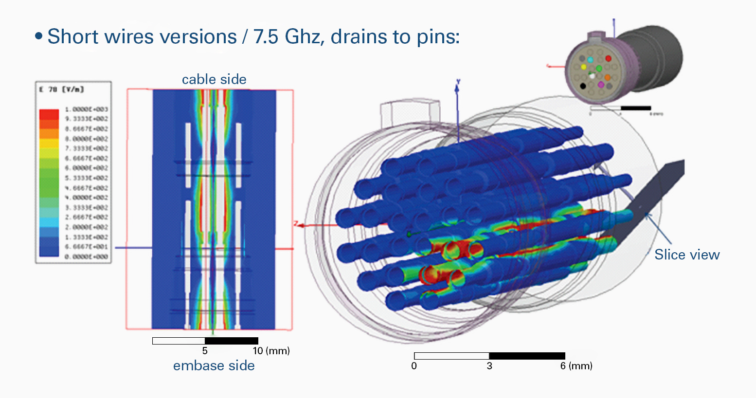
Software simulation accurately predicts data transfer rates when a specific connector and cable are tested together.
Simulation software can, for example, measure and compare the S-parameters of a cable assembly with the target values defined in a given protocol specification (e.g., USB 3.0, HDMI, and Ethernet). If one of the parameters fails, an iteration loop will be made on the design until the cable assembly fulfills all protocol requirements. At this time, the product can be declared protocol compatible.
High-Speed Data Connectivity
Copper beats wireless for speed, and fiber optics beats copper for the amount of data that can travel quickly. So, don’t overlook fiber options when you have a need for data speed. It is quite possible that while determining the need for data speed, you’ll be evaluating a combination of wireless, copper wire, and fiber optic connectivity solutions — especially for larger projects. As connectivity options expand, you may even want to use all three at various points in the ecosystem. Careful consideration needs to be given to each segment of your connectivity solution in order to achieve the best possible data transfer rates in application that require high-speed performance.
For more information, visit Fischer Connectors.
Like this article? Check out our other Ethernet, Fiber Optics, Networking, and Connector Basics articles, our Wire and Cable Assemblies and Datacom/Telecom Market Pages, and our 2021 and 2020 Article Archives.
- Three Things to Consider When You Have a Need for Data Speed - April 6, 2021