Design Considerations, Tips, and Techniques for 5G Coaxial Interconnects
The adoption of 5G devices comes with an increase in performance pressures for connector technologies. Miniature coaxial connector products in microstrip and stripline versions are rising to meet stringent performance, space, and cost objectives.
By Alan Kinningham, SI Design Team Manager, Travis Amrine, Global Industry Marketing Manager, and Adam Nagao, Signal Integrity Engineer – R&D, I-PEX Connectors coaxial
The installation of 5G networks is well underway and the significant computing demands these architectures exert will push the boundaries of current component technologies. These new pressures will need to be balanced with new connectivity solutions. Equipment and component makers are challenged to produce products that can deliver higher performance and higher-frequency operation in a cost- and size-constrained environment. The shadow of cost-containment looms large over every discussion of performance requirements. A successful product launch must satisfy each of the three main requirement areas — cost, size, and performance.
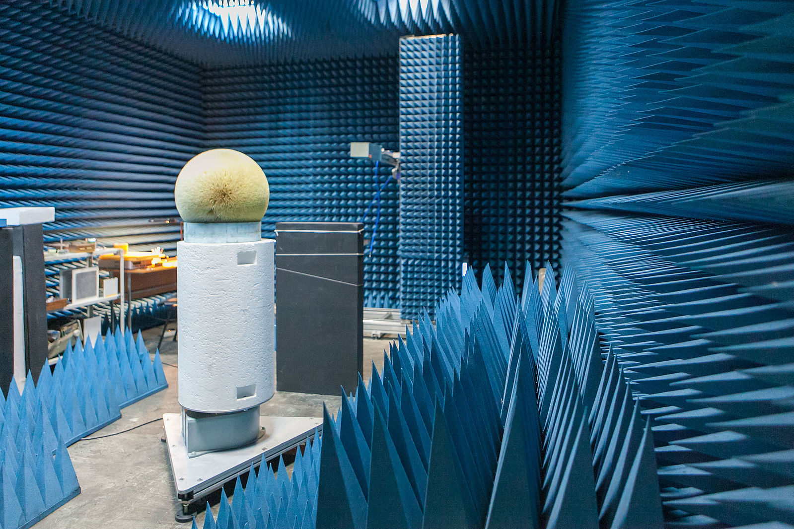
Figure 1: 5G-enabled devices are comprised of multiple miniaturized subsystems that must be electrically isolated from one another to achieve electromagnetic compatibility. Validation testing is conducted in anechoic chambers like this one. (Image courtesy of ITMO University per CC BY-SA 4.0)
Meeting Cost, Size, and Performance Targets in 5G Devices
To achieve the multi-gigahertz electrical performance 5G networks require, engineers must isolate internal and external sources of electromagnetic interference (EMI). This unique challenge becomes even clearer when one considers that a 5G-enabled handheld device contains multiple subsystems that must be electrically isolated from each other. Locating one subsystem designed for efficient radiation mere millimeters away from the sensitive logic CPU core or passive antenna can potentially produce an electromagnetic compatibility (EMC) nightmare. Requirements for physical miniaturization, performance, and cost further complicate component selection. Traditional high-performance coaxial cables and machined connectors might seem like a good choice for mitigating unintended EMI leakage from both immunity and interference standpoints at first glance, but they fail to meet both cost and size requirements. However, a growing array of cost-effective options can help solve interference problems while satisfying size and cost requirements.
Miniature coaxial connectors (in both microstrip and stripline versions), together with cable grounding and wire management tools, are one such collection of progressive EMI solutions. Small, shielded, and inexpensive, these components play a key role in the successful product engineer’s strategy for achieving system EMI compliance.
Industry-standard procedures for many engineering designs strive to achieve performance targets by using components with high potential to successfully meet size and cost targets. As frequencies continue to rise, strategies for EMI reduction and isolation must also be included in the initial design. Fortunately, progressively effective solutions that aid mitigation of EMI system emissions to acceptable levels are now available.
The first effective component choice is a low-cost, microstrip version of a board-to-cable solution (Figure 2). It provides basic micro-coaxial connection to a PCB microstrip structure. Microstrip performance can be acceptable for certain RF designs and occupies only two metal layers on the PCB, which reduces PCB cost and thickness, but it may not suppress EMI radiation at sufficient levels to achieve full compliance at higher frequencies.
In cases where microstrip transmission lines are insufficient to meet EMI performance requirements, a three-layer stripline transmission-line structure — as seen in low-profile, high-performance RF stripline connectors (Figure 7) — may provide a suitable alternative.
In high-performance environments that require even more effective EMI countermeasures, the addition of an SMT grounding clip (Figure 4) can help. These clips suppress EMI-induced current on the cable shield, offer improved cable routing management using minimal PCB space, and are an effective, low-cost tool that greatly suppresses EMI emissions while also minimizing PCB layout redesign requirements.
The associated improvements in shielding effectiveness, beginning with the addition of the SMT cable ground clips, are readily apparent in a comparison of Figures 5 and 8. The shielding performance of these four cases are examined more closely using a high-frequency structure simulator (HFSS), the Ansys HFSS 3D EM Simulation.
Case 1A: Microstrip Transmission Lines for Low-Cost EMI Performance
The microstrip transmission line case is set up with the microstrip RF connector and simulated in HFSS. As seen in Figure 3, the microstrip structure allows radiation to escape the guided wave structure.
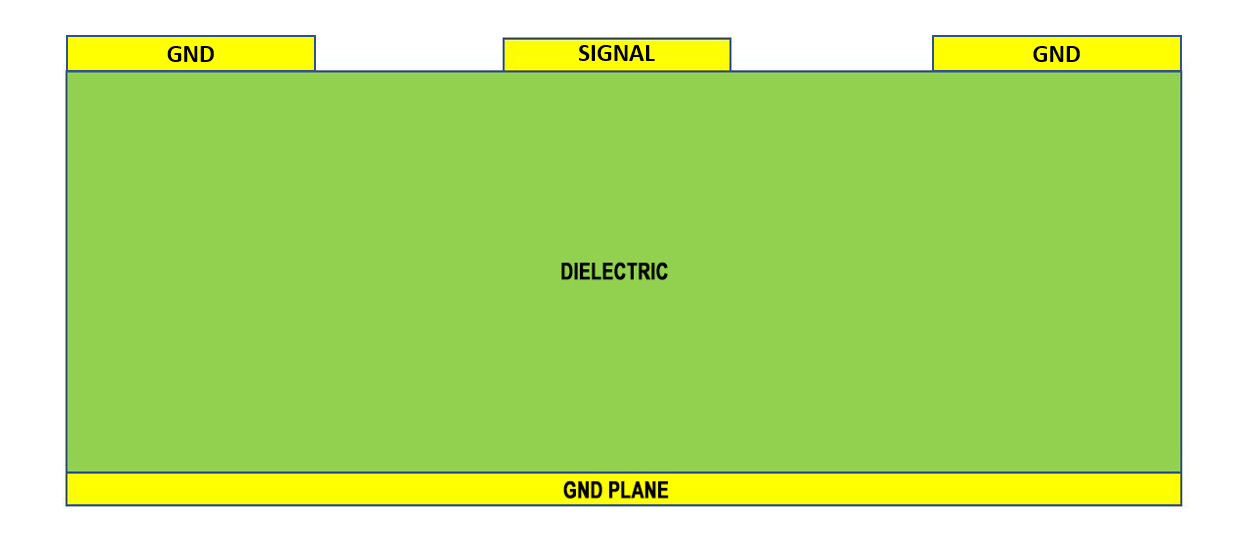
Figure 2: A cross-sectional view of a microstrip structure.
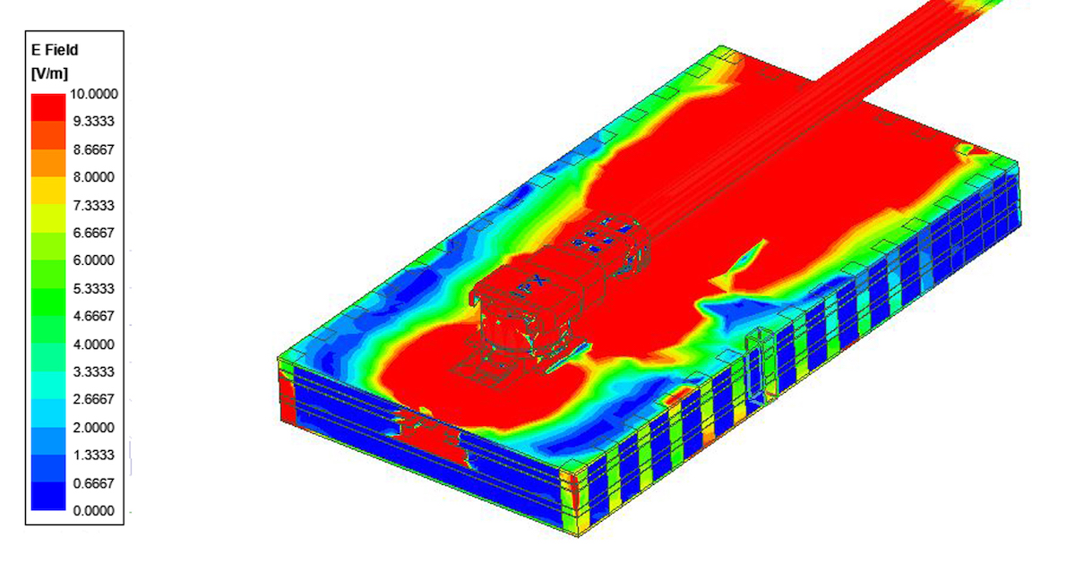
Figure 3: An I-PEX MHF 4L micro-coaxial RF connector attached to a microstrip waveguide structure that has inherent radiation properties. This solution still exhibits deficiencies in EMI suppression.
Case 1B: RF Microstrip Connector with Additional SMT Ground Clip
With the addition of the SMT ground clip, the EMI radiation is localized to the area around the launch point and significantly reduced along the length of the microstrip line (Figure 5).
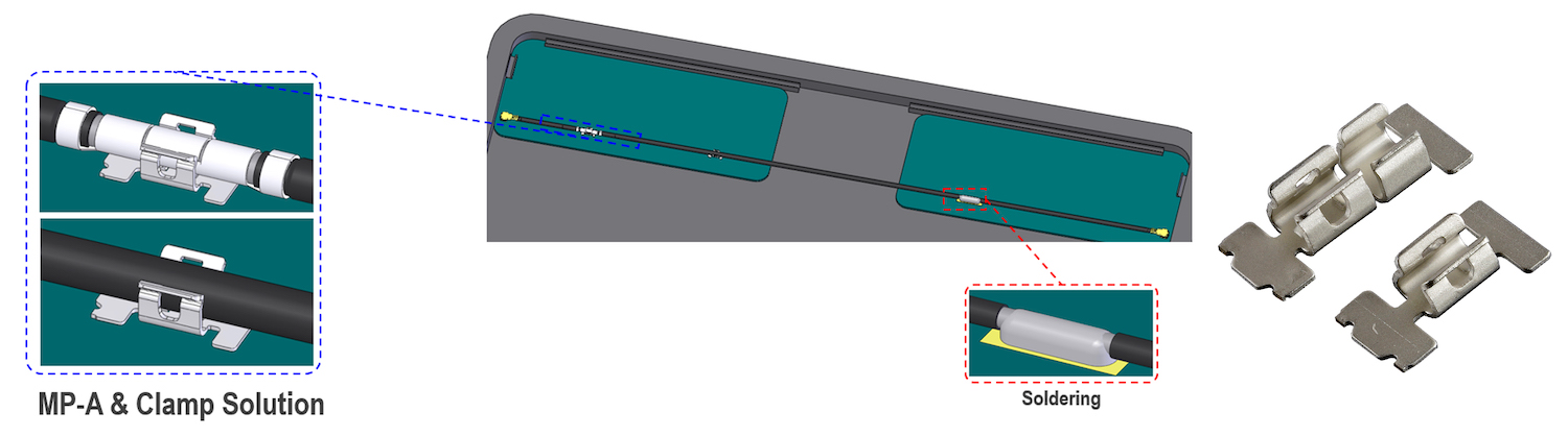
Figure 4: EMI simulation case 1B uses the I-PEX MP-A SMT ground clip to drain interference currents from the micro-coaxial cable shield to the PCB ground plane.
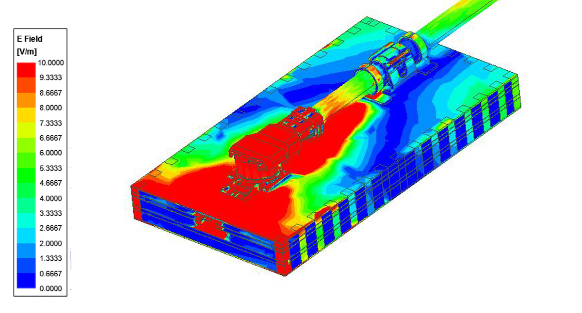
Figure 5: EMI simulation case 1B uses the I-PEX MP-A SMT ground clip to drain interference currents from the micro-coaxial cable shield to the PCB ground plane, thereby limiting the area of EMI leakage.
Case 2A: Stripline Transmission Lines and RF Stripline Connector for Improved EMC
Three-layer stripline transmission-line structures (Figure 6) are commonly used alongside specialized stamped connector solutions (Figure 7) in robust, premium-value 5G designs. The signal conductors in these RF stripline connectors are completely contained within the boundaries defined by ground layers, on both sides of the signal layer, and provide the best shielding in a PCB design.
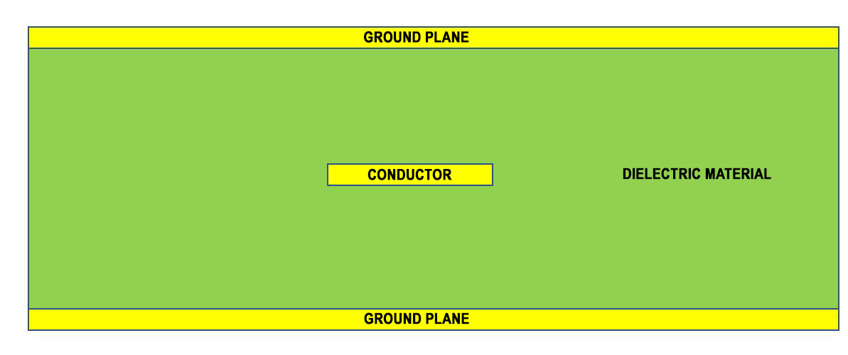
Figure 6: A cross-sectional view of a three-layer stripline transmission structure.
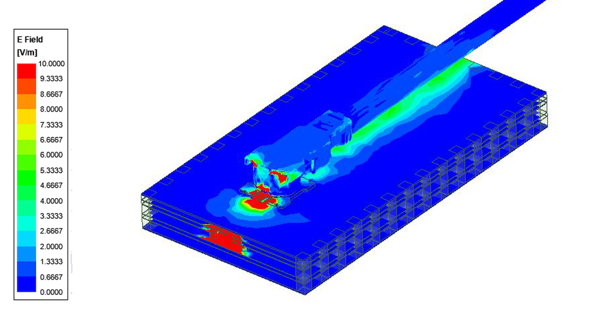
Figure 7: The I-PEX MHF 7S micro-coaxial RF connector and cable attached to stripline transmission structure allows very small levels of EMI leakage onto the upper PCB ground layer.
Case 2B: Stripline Transmission Lines and RF Stripline Connector with Additional SMT Grounding Clip for the Most Effective EMI Suppression
For extremely sensitive 5G systems that require the highest EMI shielding-suppression performance, the addition of the SMT grounding clip further enhances the performance of the RF-shielded stripline and RF stripline connector (Figure 8) pairing.
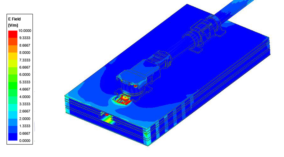
Figure 8: The highest level of EMI mitigation is achieved with three-layer stripline transmission lines, a lockable RF stripline connector, and an SMT grounding clip.
In conclusion, successive improvements in the EMI shielding effectiveness can be achieved through the use of microstrip RF coaxial connectors (Figure 3), microstrip RF coaxial connectors with SMT cable ground clips (Figure 5), stripline RF coaxial connectors (Figure 7), and stripline RF coaxial connectors with SMT cable ground clips (Figure 8).
The adoption of 5G devices comes with an increase in performance pressures for connector technologies. Innovative stamped connector products are rising to the challenge and offering strategic solutions that can help designers achieve stringent performance, space, and cost objectives. This technological evolution is sure to inspire novel solutions for 5G devices both now and in the foreseeable future.
For more information, visit I-PEX online.