What are Triax Connectors?
Meet the Connector: Triax Connectors
By adding a third conductor, these high-performance RF connectors work with triaxial cable to increase signal integrity and reduce noise in high-precision applications in busy environments that call for increased shielding.
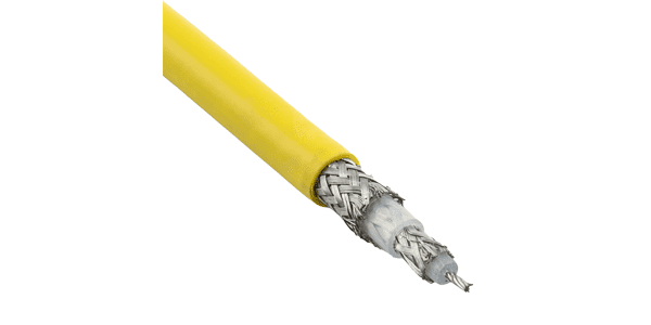
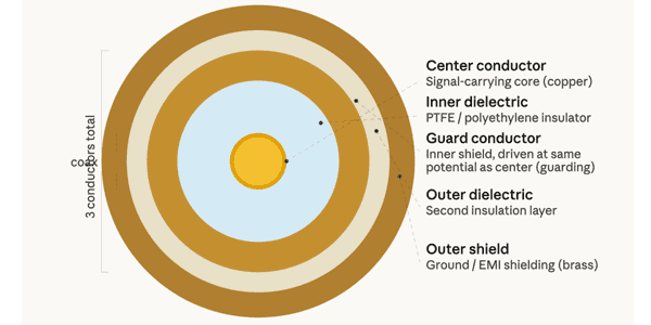
A triax connector (also called a triaxial connector) is a specialized coaxial connector that adds a third conductor — essentially a coaxial connector within a coaxial connector. It’s commonly used in precision measurement, instrumentation, and low-noise applications where signal shielding and guard conductors are critical. The inner conducting layer — the guard conductor — sits between the signal core and the outer shield. In a standard coax you have signal + ground. A triax adds a third, independently driven conductor in the middle. Similar to BNC connectors, the TRB connector is essentially the twinax/triax equivalent of a BNC.
The triaxial connector emerged from the broader coaxial connector ecosystem in the 1950s–60s. Cinch is generally regarded as a major contributor; the company developed a specific implementation of triax (concentric vs. twin pin), which was later adopted by the MIL-PRF-49142 standard.
Design Notes
Standards: Triax connectors are governed across several overlapping standards depending on application:
- Military formats follow MIL-DTL-38999, ARINC 404, and ARINC 600
- Triax contacts meet or exceed MIL-C-39029/90 & /91
- Broadcast triax is governed by SMPTE and IEC 60512 series
- Test voltages reference IEC 60512-4-1, current ratings IEC 60512-5-2, and contact resistance IEC 60512-2-1 and -2-2
- Environmental testing follows MIL-STD-202 and IEC 60068
Electrical attributes
Triax connectors support impedances typically of 50 Ω or 75 Ω (matching standard coax systems), and they provide significantly better shielding effectiveness than coax because signals are doubly isolated. The three-conductor geometry allows voltage tripling in some configurations and supports very low-noise, low-leakage signal transmission. Capacitance between layers is typically in the range of tens of picofarads per meter, depending on dielectric geometry.
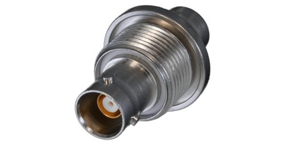
Physical attributes: The connector faces have a distinctive triple-ring appearance in cross section. Common standard types include the BNC-style triax (TNC triax) and the SHV (Safe High Voltage). Mating cycles are rated in the hundreds to low thousands, similar to precision coax.
Mounting: Straight, right-angle, cable mount, and PCB mount configurations, as well as panel mount versions. Common body styles include:
- Cable/inline mount (most common for field use)
- Panel mount with 4-hole flange
- Through-hole PCB mount (straight and right-angle)
- Bulkhead/feedthrough
- Board mount versions are available in both straight and right-angle solder termination
Mating cycles: Varies by product tier: While military-grade triax contacts may be rated for 1,000 mate/unmate cycles minimum, broadcast-grade triax can be rated for 5,000 mating cycles
Positions: Single position (one triaxial signal per connector body). However, ganged triax assemblies can allow up to 50 triax connections. Triax contacts in sizes 8, 10, and 12 can be mixed with coax, twinax, and power contacts within a single circular connector body such as a D38999.
Dimensions: Outer diameter depends heavily on form factor.
- Standard broadcast triax (8 mm cable): outer connector shell ~19–22 mm OD
- 11 mm cable version: shell ~25 mm OD
- Compatible cable center conductor diameter 1.0 mm (8 mm type) or 1.4 mm (11 mm type); inner shield diameter 4.5–6.5 mm; cable OD 8.4–11.3 mm
- Ultraminiature military contacts (size 10, 12): match standard coax contact outline, fitting standard MIL connector cavities
Contacts:
Pins: Three concentric conductors — center (signal/force), intermediate (guard), outer (ground/shield)
Spacing/pitch: Concentric geometry — no discrete pitch. Conductor separations are set by dielectric thickness (typically 1–2 mm between each conductor ring)
Height: Connector mating depth typically 10–20 mm depending on series; contact engagement length ~5–8 mm
Contact resistance: Center contact < 3 mΩ; outer contact < 0.5 mΩ; ground contact < 5 mΩ
Termination types: Solder cup, crimp, clamp, screw (inner conductor on some broadcast types), and PCB through-hole solder pin
Material specifications: Center and intermediate contacts: heat-treated beryllium copper with 50 millionths of an inch (50 µin) gold plating; outer conductor spring: heat-treated beryllium copper (not slotted brass)
Physical properties:
Insulation: PTFE is the dominant dielectric for precision and military use; polyethylene for lower-cost broadcast versions.
Shielding: Dual-shield construction provides significantly greater shielding effectiveness than single-shield coax. The guard conductor can be driven actively (voltage follower) to reduce inner dielectric leakage to near zero.
Locking mechanism: Available in both threaded and quick-disconnect versions. Broadcast types typically use a multi-start bayonet or threaded collar; military types use the locking mechanism of their host connector (e.g., D38999 triple-start thread).
Environmental properties:
IP rating/Sealing mechanism: IP68 when mated or with fitted sealing caps per IEC 60529
Ruggedization: Vibration tested to 10–2,000 Hz, 1.5 mm or 20 g with no discontinuity > 1 µs; corrosion tested 96 hours in 5% salt spray at 35 °C
Temperature range: Military triax contacts: −65 °C to +165 °C; Broadcast types (Fischer 1051-A004-3/4): −55 °C to +135 °C; outdoor-rated variant (1051-A004-9): −40 °C to +85 °C
Electrical properties:
Voltage AC/DC: Test voltage center to outer: 1.7 kVAC; outer to ground: 1.0 kVAC (broadcast, mated)
For military contacts: center to intermediate: 1,000 Vrms minimum (500 Vrms for size 12); intermediate to outer: 400 Vrms minimum (200 Vrms for size 12); voltage rating at sea level: 500 Vrms (200 Vrms size 12)
- Current (Amps): Broadcast type: 14 A per contact
- Military contacts: 3 A DC maximum (size 10); 1.5 A DC maximum (size 12)
Impedance options are 50 Ω, 75 Ω, and 95 Ω depending on cable type, with 75 Ω dominant in broadcast and 50 Ω in instrumentation/military.
Markets and Applications
Military and aerospace, Consumer (A/V), Industrial, Test & Measurement
Semiconductor testing, electrochemistry, precision voltage/current sourcing, and high-impedance sensor interfaces — anywhere a second isolated conductor is needed without adding a second connector.
Suppliers
Triaxial connectors are available in many variations from Cinch Connectivity Solutions, Amphenol RF, Fischer Connectors, Smiths Interconnect, and other suppliers.
Related products
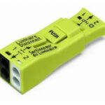
- EU Battery Regulation Prompts Design Changes for Battery Connectors - July 14, 2026
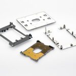
- What is an LGA Socket? - June 30, 2026
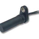
- What is a Speed Sensor? - June 23, 2026