What is a Connector Gasket?
In harsh environment conditions, connector gaskets provide protection against a variety of hazards that can put connections at risk.
Connector gaskets are sealing components installed between connector mating or mounting surfaces to provide environmental protection, electromagnetic shielding, or both. They compensate for surface irregularities and maintain sealing integrity under mechanical stress, vibration, thermal cycling, and environmental exposure. Depending on material and design, connector gaskets may prevent ingress of moisture, dust, and chemicals while also maintaining electrical continuity.
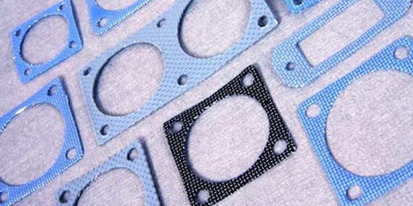
TE Connectivity offers a wide range of standard MIL connector gaskets. Different materials are available to meet the demands of EMI shielding, environmental sealing, galvanic compatibility, and chemical resistance.
Gasket types
Common gasket classes are:
- Environmental connector interface gaskets
- Panel-mount sealing gaskets
- EMI conductive gaskets
- O-rings
- Face seals
- RF connector interface gaskets
- Board-level compression seals,
Gasket types should be evaluated for their mechanical and electrical properties. For example, silicone O-rings provide environmental sealing, while wire mesh gaskets, conductive fabric-over-foam, and metal particle-filled silicones provide EMI shielding. Conductive elastomers provide both environmental and EMI shielding.
Gasket design
Materials
Depending on the application, gasket material is chosen for its ability to resist chemical exposure, temperature extremes or fluctuations, pressures, gases, and electromagnetic or electrical forces. The material should be able to deform to create a tight seal and fill the space it is designed for, accommodating slight irregularities. Some gaskets require a sealant applied to the gasket surface.
Materials include paper, rubber, silicone, metal, cork, felt, Neoprene, nitrile rubber, fiberglass, polytetrafluoroethylene (otherwise known as PTFE or Teflon), or plastic polymers (such as polychlorotrifluoroethylene), Perfluoroelastomer (FFKM), Nitrile (NBR), Hydrogenated Nitrile (HNBR), Viton, silicone (VMQ), and Fluorosilicone (FVMQ). Some applications require gaskets made from medical-grade materials.
In industrial applications, gasket material may need to withstand high compressive loads, such as pressure exerted by bolts.
Environmental conditions also play a role in choosing the right material. Fluorosilicone and silicone handle wide temperature ranges (typically -55 °C to +200 °C). Fluorosilicone or fluorocarbon (Viton) is commonly specified to maintain tensile strength and seal integrity for connectors that are near jet fuel, automotive fluids, or solvents.
Gasket material must meet strict Total Mass Loss (TML) and Collected Volatile Condensable Material (CVCM) limits to prevent optical lens or sensor contamination in aerospace or space-grade applications (such as NASA-STD-6001 compliance).
Mechanical geometry
The physical shape of the gasket determines how it deforms under load and how well it fills the sealing gland.
- Profile shape: Options include flat die-cut gaskets, O-rings, or custom molded profiles (like D-sub or rectangular shell configurations). Custom profiles often include sealing ribs to concentrate clamping force and create redundant sealing barriers.
- Aspect ratio: The ratio of the gasket’s height to its width must be optimized. If a gasket is too tall and narrow, it will topple or column-buckle under compression rather than compressing cleanly, creating paths for leaks.
Compression control and gland design
The gasket and its mating interface are designed simultaneously to ensure that the gasket seals well within the gland it sits in.
- Gland fill percentage: The gland must feature enough free volume (typically 75% to 90% gland fill) to accommodate the deflected material when fully compressed. Over-filling causes the material to extrude, damage the connector shell, or tear.
- Compression deflection: Most elastomeric gaskets require a specific compression range (typically 15-35% for environmental seals, and up to 40-50% for specialized hollow profiles) to achieve an optimal seal without inducing material fatigue.
- Compression set resistance: The material’s tendency to permanently deform over time under a load, especially across thermal cycles, must be factored into the design.
Galvanic compatibility and corrosion
A gasket with conductive fillers for EMI/RFI shielding (like silver, nickel, or carbon particles) can trigger galvanic corrosion when it touches the metal connector shell.
- Shell plating alignment: The gasket’s conductive filler must be closely matched on the galvanic chart to the connector’s shell plating (e.g., matching nickel-aluminum filled gaskets with cadmium or nickel-plated aluminum shells) to prevent moisture from creating a battery cell that accelerates corrosion.
- Dual-elastomer (co-molded) designs: High-reliability designs often use a “co-extruded” or “dual-elastomer” gasket. The inner track features a conductive material for EMI shielding, while the outer track is a non-conductive environmental fluorosilicone that keeps moisture out of the galvanic junction entirely.
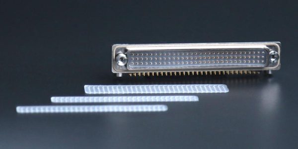
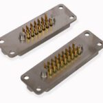
Nicomatic’s silicone interfacial gasket, available for its CMM and EMM series, is a simple yet highly effective solution. Positioned between the two connector halves, this accessory acts as a protective barrier, strengthening system reliability even in the most severe environments.
Manufacturing and assembly constraints
Fabrication and handling affect the gasket’s final dimensions and performance.
- Molding vs. die-cutting: Die-cutting from sheet stock is cost-effective but is limited to flat geometries and creates material waste. Injection or compression molding allows for complex 3D features (like integrated alignment tabs) but introduces knit lines where the material meets in the mold, which can be mechanical weak points.
- Form-in-Place (FIP) alternatives: Loose or flimsy ultra-high-density or miniature connectors can be impossible to handle. For these, designers often opt for FIP technology that robotically dispenses and cures a continuous bead of conductive silicone directly onto the connector flange.
An important engineering trade-off is balancing the need for increasing clamping force, which improves EMI shielding and environmental sealing, and over-tightening, which risks bowing the connector flange between the fasteners. This flange distortion lowers the compression mid-span, frequently causing sealing failures right between the screws.
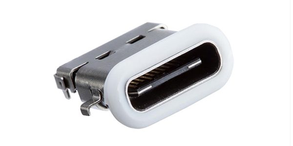
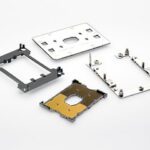
Amphenol LTW (ALTW) connector gaskets and O-rings are precision-engineered sealing components designed to maintain environmental protection up to IP68/IP69K. ALTW offers a range of elastomer materials selected for specific chemical compatibility and environmental requirements, including EPDM, Viton (FKM), silicone (VMQ), and NBR (Nitrile). Additional material options are available to address specialized industrial, marine, transportation, renewable energy, and chemical-processing applications.
Testing
Hot compression test
The hot compression test is one of the most widely accepted methods of testing a gasket material’s ability to withstand compressive loading. Manufacturers of gasket materials usually provide or publish the results of these tests to help customers to select the appropriate gasket according to their needs.
Ingress Protection (IP) & fluid sealing tests
These tests measure the immediate physical barrier performance of the gasket against liquid and solid particulate entry.
- IEC 60529 / ISO 20653 (IP Ratings):
- IP67: Immersion testing in water up to 1 meter for 30 minutes.
- IP68: Continuous submersion at a manufacturer-defined depth and duration.
- IP69K: High-pressure (up to 10,000 kPa / 1,450 psi), high-temperature (80 °C) water jet washdowns from multiple angles. This simulates heavy industrial and food-processing cleaning.
- MIL-STD-810, Method 512 (Immersion) & Method 506 (Rain): Evaluates the seal when exposed to blowing rain or differential pressures encountered while submerged.
Thermal & environmental aging tests
Elastomeric materials used in gaskets (like fluorosilicone, EPDM, or Viton) degrade over time when subjected to temperature extremes, causing them to lose their sealing force (compression set).
- EIA-364-17 / IEC 60068-2-2 (dry heat / temperature life): Bakes the connector with the gasket installed at elevated temperatures (e.g., 125 °C or 200 °C) for extended periods (typically 250 to 1,000 hours). This accelerates aging to check if the gasket becomes brittle, develops cracks, or loses resilience.
- EIA-364-32 / IEC 60068-2-14 (thermal shock): Rapidly cycles the connector between extreme low and extreme high temperatures (e.g., -65 °C to +125 °C) within minutes. It forces structural expansion and contraction, testing whether the gasket tears or slips out of its groove.
- IEC 60068-2-38 (composite temperature/humidity cyclic test): Exposes the component to high humidity combined with sub-zero temperature excursions. This forces a “breathing” effect that tests if moisture can bypass the gasket during freeze-thaw cycles.
Corrosion & chemical resistance tests
Harsh environments often feature airborne salt, corrosive gasses, or industrial fluids that can chemically degrade elastomeric compounds.
- EIA-364-26 / MIL-STD-810, Method 509 / IEC 60068-2-52 (salt spray / salt fog): Atomizes a 5% NaCl solution into a continuous fog over 48 to 96+ hours. While primarily a plating test for connector shells, it tests whether the gasket prevents the salt fog from bridging the internal contacts and whether the gasket material itself degrades.
- MIL-STD-810, Method 504 (contamination by fluids): The gasket is exposed to or submerged in representative field fluids—such as jet fuel (JP-8), hydraulic fluid, lubricating oils, antifreeze, and cleaning solvents—to ensure it does not swell, soften, or dissolve.
- EIA-364-65 (mixed flowing gas): Exposes the connector to corrosive gases (NO2, H2S, Cl2, SO2) at controlled humidity. It evaluates the gasket’s ability to provide a gas-tight seal to protect internal contact interfaces from tarnish.
Mechanical endurance & vibration tests
Vibration can cause physical displacement or micro-motion between mating connector halves, which can wear down or dislodge a gasket.
- EIA-364-28 / IEC 60068-2-64 (random vibration): Subjecting the connector to intense broadband random vibration profiles (often across frequencies from 5 Hz to 2,000 Hz) while under thermal stress. The gasket must maintain its seating profile and continuous contact pressure during the dynamic motion.
- EIA-364-09 (durability): Measures the effects of repeated mating and unmating cycles. This determines if friction or shearing forces against the receptacle face shred or prematurely wear out the gasket material.
Engineers typically perform these tests sequentially on the same connector sample (e.g., Thermal Shock —> Vibration —> Salt Fog —> IP68 Immersion). This ensures the ingress testing at the very end evaluates a realistically weathered, stressed gasket rather than a pristine factory sample.

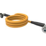
The Pisces Series from IntelliConnect, a Trexon company, features an O-ring gasket design.
STANDARDS
Multiple standards apply to the design and use of connector gaskets, depending on the industry and application, including these primary standards:
Military & aerospace: Military specifications dictate high-performance requirements for ruggedized connectors (e.g., MIL-DTL-38999 and MIL-DTL-83723). Conductive elastomer gaskets often adhere to the MIL-DTL-83528 standard for EMI/RFI shielding.
Material safety: General rubber, elastomeric, and sealing materials must often comply with ANSI/UL 157 (Safety Standard for Gaskets and Seals) and ASTM F104 for non-metallic gasket classification.
Automotive: Electrical and mechanical connector gaskets commonly follow global guidelines like IEC 60529 (dust and water ingress) and ISO 20653 (road vehicle specific), ensuring dimensional accuracy and performance under harsh environmental stress.
General electronics: Electrical connector testing often references EIA-364 test procedures (e.g., for durability, insertion force, and shock) which evaluate the integrated performance of mated connectors and their seals.
SUPPLIERS
TE Connectivity, Nicomatic, Milnec, and many specialty companies.
MARKETS & APPLICATIONS
Military, Aerospace, Automotive, Telecom, Datacom, Industrial, Medical
Tactical radios, ruggedized field computers, missile guidance systems, naval shipboard communications, and ground vehicle electronics; avionics bays, cockpit flight control systems, landing gear sensors, radar arrays, and engine control units (ECUs); battery management systems (BMS); outdoor cellular base stations, 5G/6G small cells, antenna feeds, and high-density fiber optic/copper patch panels in data center server racks; robotics sensors, programmable logic controllers (PLCs), wind turbine pitch control systems, solar inverters, and oil/gas drilling instrumentation; diagnostic imaging machines (MRI, CT scanners), patient monitors, surgical tools, and laboratory analysis equipment.
Like this article? Check out our other Meet the Connector and Connector Basics articles, our Military and Aerospace Market Page, and our 2026 Article Archives.
Subscribe to our weekly e-newsletters, follow us on LinkedIn, Twitter, and Facebook, and check out our eBook archives for more applicable, expert-informed connectivity content.
- Three Companies, One Mission: Reduce Plastics in Electronic Connectors - July 28, 2026
- Cable Accessories and Tools Product Roundup - July 28, 2026
- Extreme Temperature Innovations for Aerospace and Defense - July 21, 2026