What is an IEC 61076-2-117 Connector?
The IEC 61076-2-117 standard specifying shielded M12-M40 single cable, hybrid (combined signal, power, and data) connectors for industrial applications addresses the demand for faster and more reliable connections.
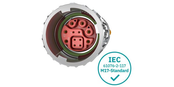
The IEC 61076-2-117 standard addresses the demand for faster and more reliable connections in industrial environments, specifying shielded M12-M40 single cable, hybrid (combined signal, power, and data) connectors for industrial applications. It defines the mechanical interface as well as electrical parameters, EMC requirements, and degrees of protection up to IP67. The standard was first released May 26, 2023, and progressed to the Final Draft International Standard (FDIS) stage on April 17, 2026, when it became available for pre-release. The 2023 release marked a significant step in standardizing tool-less installation for industrial communication and power, significantly reducing assembly time and the risk of improper tightening. The “-117” sub-standard specifically addresses the push-pull version. However, connectors such as Phoenix Contact’s M17 Pro hybrid connector, which features a one-click fast-locking mechanism rather than push-pull, are in accordance with the standard due to its interface and pin assignment compliance. This ensures that the electrical layout is standardized for hybrid communication.
A major feature of this standard is backward compatibility. Most IEC 61076-2-117 ports are designed to be “dual-compatible,” meaning the port has internal locking grooves for push-pull cables but also retains external threads so a standard M12 screw-type cable can still be used.
Connector Configurations
While previously power and signal were in separate cables, IEC 61076-2-117 specifies the connector configurations for combining power, signal, and data into a single interface. Connectors are according to this standard to handle high-speed data transmission (often Ethernet-based) alongside auxiliary power. The most common layouts include:
- 8-Pole Hybrid (4+4) features four pins for data (typically D-coded for 100 Mb/s or X-coded for up to 10 Gb/s) and four pins for power.
- Y-coding and X-coding patterns provide specific internal shielding and pin arrangements to prevent crosstalk between the power lines and the data lines in the same connector shell.
- Integrated 360° shielded design ensures electromagnetic compatibility (EMC), which is vital when power and data are in close proximity.
In industrial environments, including robotics and automotive manufacturing, these configurations address several challenges.
- Miniaturization and space savings (one-cable automation)
Space is limited in applications like robotic arms and compact sensors. The hybrid configuration replaces two cables and ports with one. This reduces the footprint on the device and allows for smaller, lighter machinery.
- Speed and “blind” mating
The push-pull/fast-locking mechanisms improve the speed and accuracy of mating, particularly where visibility is limited or connections are made in hard-to-reach locations. The -117 configuration provides an audible “click,” ensuring the connection is IP65/IP67 sealed, without tools. This is a major improvement over screw threads which can be over- or under-tightened.
- Vibration resistance
In heavy industrial applications, constant vibration can loosen traditional screw-type connectors over time. The mechanical configuration of the -117 standard uses a spring-loaded locking mechanism that remains secure under high-vibration loads, preventing intermittent data loss or power arcing.
- Decentralized power distribution
The hybrid configuration supports the trend of decentralized automation. Instead of running all cables back to a central control cabinet, these connectors allow “daisy-chaining” of power and data from one device to the next on the factory floor, significantly simplifying the wiring architecture.
- Reducing installation errors
The standardized and interoperable configurations eliminate the risk of installation errors that could lead to pin damage or electrical shorts when a proprietary connector is inadvertently forced into another manufacturer’s port.
The compact M17 hybrid connectors from Phoenix Contact are suitable for space-critical, modular designs. This makes them ideal for developers searching for robust and standard-compliant single-cable solutions.
Materials & Construction
Materials are selected to prevent “fretting corrosion” (damage caused by micro-vibrations) and ensure that the power side of the hybrid connector doesn’t interfere with the high-speed data side, which is critical for real-time spatial awareness and sensor feedback.
Shell and Housing Materials
The outer shell must provide structural integrity and resistance to environmental stressors.
Metal shells: Usually made of nickel-plated brass or zinc die-cast. These materials are chosen for their durability and superior EMC shielding.
Plastic/composite shells: In some lightweight or corrosive-resistant applications, high-performance thermoplastics (like PA66) are used. They must meet the mechanical locking requirements of the standard.
Knurled nuts/locking rings: For the push-pull mechanism, these components often use stainless steel or reinforced alloys to ensure the locking “teeth” do not wear down after repeated mating cycles.
Contact material and plating
To handle high-speed data alongside power, the contacts are engineered for low resistance and high conductivity.
Base material: Typically a copper alloy (such as phosphor bronze or brass), which provides excellent conductivity and spring properties.
Plating: The contact surface is almost always gold over nickel. Gold, which does not oxidize, ensures that low-voltage data signals remain free from noise, interference, and degradation over the life of the connector.
Insulators and dielectrics: The internal “insert” that holds the pins in place must be a high-performance insulator.
Materials: Common materials include TPU (thermoplastic polyurethane) or PBT (polybutylene terephthalate). These materials must have high dielectric strength to prevent arcing between the power pins and the data pins. They must also be flame-retardant (often meeting UL 94 V-0 standards).
Sealing and Environmental Protection
Specific sealing components ensure the construction achieves the standard’s required IP65/IP67 (or even IP69K) ratings.
O-Rings and gaskets: FKM (Viton) or NBR (Nitrile rubber) ensure that once the push-pull mechanism “clicks” into place, the connection is airtight and watertight.
Potting/Encapsulation: Potting with epoxy or resin at the rear of the connector (where the cable enters the shell) prevents moisture from “wicking” into the device through the cable jacket.
Construction of the push-pull mechanism
The standard is defined by a specific mechanical assembly.
Spring-loaded sleeve: The construction includes an internal spring mechanism that allows the outer sleeve to retract and snap forward.
Locking hooks/grooves: A system of locking hooks engage with a specific groove on the port. This allows for blind mating, where the user can feel and hear the connection without needing to see the alignment.
Contact Configurations
8-pole (Hybrid) data and power: Max. current ~6A (Power Pins); Max. voltage 30V – 60V.
12-pole high density signal: Max. current ~1.5A – 2A; Max. voltage 30V.
4/5-pole power/basic signal: Max. current ~4A – 12A; Max. voltage 60V – 250V
| Identification & Standards | |
| Military / Industry Spec | IEC 61076-2-117 |
| Governing Body | IEC (International Electrotechnical Commission) |
| Standard Status | Draft / Pre-release international standard (FDIS stage, 2026) |
| Original Issue Date | 05-26-2023 |
| Current Revision & Date | Edition 1.0; 04-17-2026 |
| Related To | IEC 61076-2-111 (M12 Power) |
| Mechanical Specifications | |
| Shell / Housing Shape | Circular |
| Shell Material(s) | Metal (Nickel-plated Brass/Zinc alloy) or Thermoplastic are commonly used, though not specified. |
| Shell Finish / Plating | Manufacturer specified |
| Overall Dimensions | Varies by size (M12, M17, M23, M40) |
| Shell Size Codes Available | M12, M17, M23, M40 |
| Mounting Type(s) | Panel mount; PCB; Bulkhead; In-line |
| Plug Types | Straight; Right-angle |
| Receptacle Mounting Styles | End flange; Locknut; Bulkhead |
| Mating Cycles (rated) | Not specified |
| Locking Mechanism | Quick-locking or Screw-locking (M-threads) |
| Keying / Anti-mismating | Multiple coding types (e.g., Type 1, Type 2) |
| Weight (typical) | Varies by shell size and material |
| Contact Specifications | |
| Contact Count (range) | Hybrid configurations are supported, but exact contact ranges are manufacturer dependent. |
| Contact Size(s) | Power (up to 70A sizing) and Signal/Data (up to 600 MHz) |
| Contact Pitch | Dependent on specific coding/insert |
| Contact Material | Copper alloy |
| Contact Plating | Gold over nickel is common but not specified. |
| Contact Gender | Pin / Socket / Mixed (Hybrid) |
| Termination Method(s) | Crimp, solder, PCB through-hole are common implementations |
| Current Rating (per contact) | Up to 70 A |
| Voltage Rating (working) | Up to 600 V AC/DC |
| Dielectric Withstanding Voltage | Manufacturer and application dependent |
| Insulation Resistance (min) | ≥100 MΩ |
| Special Contact Types | Hybrid: Power + Signal + Data (SPE, Fast Ethernet, GigE) |
| Sealing & Environmental | |
| IP Rating | Dependent on connector design, but often IP65 / IP67 (when mated) |
| Operating Temperature Range | Manufacturer and application dependent |
SUPPLIERS
Phoenix Contact confirmed; more expected
MARKETS & APPLICATIONS
Industrial, Automotive, Transportation
Industrial automation and robotics, decentralized I/O modules, conveyer and material handling, automotive manufacturing and e-Mobility, EV battery management systems (BMS), production line infrastructure, solar and wind power, battery energy storage systems (BESS), railway, passenger information systems (PIS), video surveillance,
RELATED PRODUCTS
Like this article? Check out our other Meet the Connector and Connector Basics articles, our Military and Aerospace Market Page, and our 2025 and 2026 Article Archives.
Subscribe to our weekly e-newsletters, follow us on LinkedIn, Twitter, and Facebook, and check out our eBook archives for more applicable, expert-informed connectivity content.
- Extreme Temperature Innovations for Aerospace and Defense - July 21, 2026
- Connectors for Soldier Systems Product Roundup - July 21, 2026
- July 2026 Connector Industry News - July 21, 2026