What are Coaxial Connectors and How do They Work?
Meet the Connector: Coaxial Connectors
(Note: This article focuses on cable-to-cable and cable-to-panel applications.)
A coaxial connector has an inner conductor that is enveloped by a concentric conducting sleeve, with the conductor and shield separated by an insulating material; hence the term “coax” or “coaxial” connector. (Not all RF [radio frequency] connectors are coax, but all coax are RF connectors.) They can be for cables or board-to-board or cable-to-board applications. Coax connectors transmit analog signals while minimizing RF signal losses and work from DC to high-megahertz frequencies. Cable coax connectors are used with specific coaxial cables to take advantage of common impedance and shielding. Coaxial connectors are available in hundreds of versions. Since they are in-line, single circuit connectors and adapters are available to connect between different series.
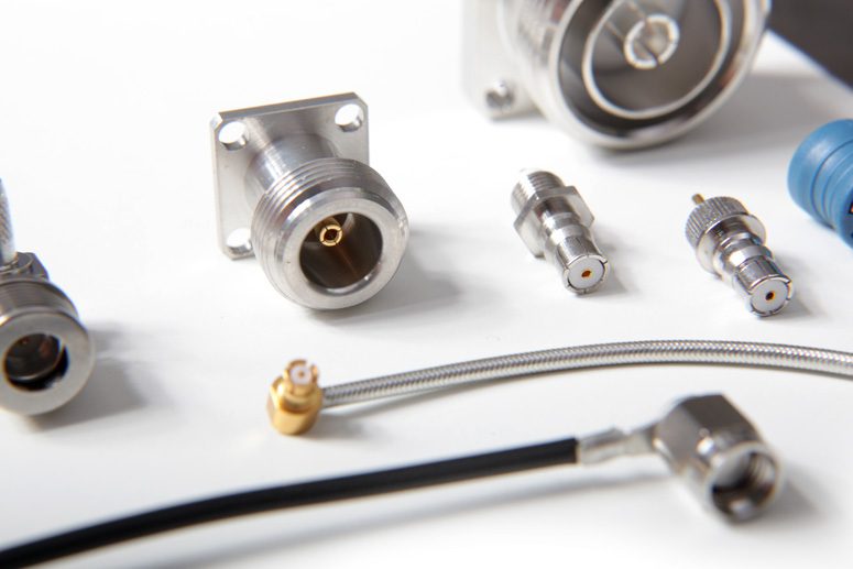
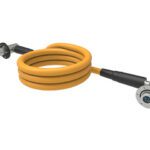
Coaxial connectors and cable assemblies from IMS Connector Systems
How They Work
As a carryover from radio applications, most cabled coax connectors have a pin/male center and are called plugs, while the mating receptacles have female/socket contacts and are called jacks. A coaxial connector, in its simplest version, consists of a signal pin, surrounded by a dielectric insulating material, which is then enclosed in a metal shield, usually the outside case of the connector. The center signal pin is usually a gold-plated, beryllium copper contact, which mates to a female contact with similar base metal and platings. These two contacts would then be soldered or crimped on to the center conductor of a coaxial cable. The center pins are surrounded by an insulating dielectric which is usually Teflon, although other materials can be chosen to provide the desired performance. The final component is the cable shield, or housing of the connector. This is designed to terminate to the shield of the coax cable, by solder, crimp, or clamping. The shield is used primarily as a barrier to outside interference.
Historical Development
Current microwave engineering grew out of the effort put into radar development in the 1930s. Waveguides pre-dated this period and received attention during WWII. After 1945, new equipment that required greater bandwidth, less weight, and smaller size, led to the development of the first standardized coaxial connectors. In the early 1940s, the primary coaxial connector in use was the UHF connector developed by E. C. Quackenbush of the American Phenolic Company (today known as Amphenol). UHF coaxial connectors were established for “low frequency” 0.6 to 300 MHz radio industry applications. UHF is an acronym for Ultra High Frequency because at that time 300 MHz was considered high frequency. Threaded UHF connectors became popular due to ease of mating/assembly. They are still used and produced worldwide today.
Mini UHF RF coaxial connector by Amphenol RF, stocked by DigiKey Electronics
Standards
Joint military and industry standards committees were formed to define RF coaxial connectors. Currently, MIL-PRF-39012 and MIL-STD-348 are the primary specifications for most coaxial connectors. In addition, MIL-DTL-17 is the governing standard for MIL-Spec coaxial cables. There are equivalent IEC and other international standards. Precision coax connectors for critical test and calibration applications are per IEEE standard 287.
Popular Coaxial Connector Types
N, C, BNC, TNC, and other coax series have been standardized. The popular SMA started as the BRM (for Bendix Research Miniature) in 1958, followed by SSMA, SMB, SMC, and others. The Type N connector, with a threaded coupling nut with 5/8” UNEF 24 turns per inch thread, met the need for a durable, weatherproof, higher power, and higher frequency connector. Type N was named for work by standards committee member Paul Neill of Bell Laboratories (New York City). Originally for DC to 1 GHz, today versions are available for up to 11 and 18 GHz.
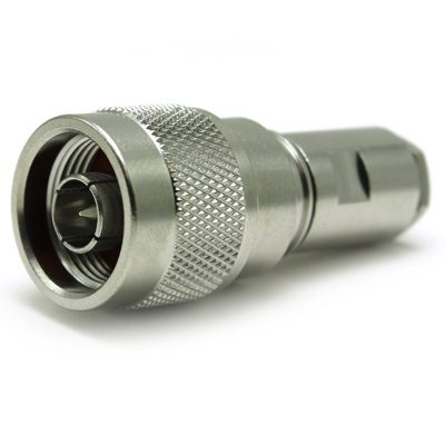
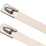
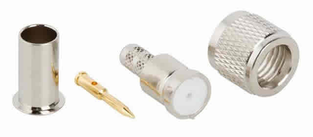
COAX Connectors N Type 50 ohm Plug IP68 sealed to 10 meters x 4 Hours Un-Mated. The crimp bullet contact and center contact are silver-plated and the outer body is white bronze for use in harsh environments. The connector is internally sealed and using a top hat clamp system, making this connector IP68 mated or un-mated.
Neill and Carl Concelman of Amphenol jointly developed the quick-connect (bayonet coupling) BNC connector to meet the demand for smaller connectors to work with the new smaller coaxial cables. The “N” and “C” came from their initials, and “B” was either for “baby,” because of its smaller size, or for “bayonet.”
After CATV F and specials, the most popular coax connector in terms of dollar sales is the SMA. SMAs are threaded coupling connectors, available worldwide in many versions, including a variety of termination options, different levels of environmental sealing, and a range of electrical performance. The SMA is smaller than the Type N, with a 0.250” diameter threaded (36 threads per inch) barrel.
Higher performance SMAs usually use internal interference-fit discs to secure components in position and have field-replaceable termination. A slightly smaller version is available termed SMC, while a bayonet coupling version is offered by some suppliers, called SMB, for DC to 6 GHz. The SMB interface was adopted for use in automotive connectors called FAKRA and there is a smaller mini-FAKRA that operates to 17 GHz.
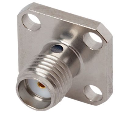
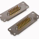
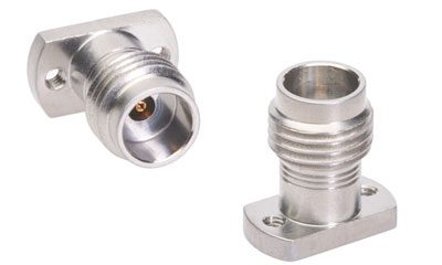
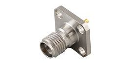
4-Hole Flange Mount SMA, epoxy captured (indicated by the black hole where epoxy is injected), with stainless steel housing and low VSWR (for good) performance to 18 GHz, from SV Microwave (Amphenol)
Why 50 ohm impedance?
The coaxial cable impedances in high-power, high-voltage, and low-attenuation applications were studied at AT&T Bell Laboratories in 1929. The best impedance is within 52 and 64 ohms, while maximum power handling is at 30 ohms. Minimum attenuation was with an impedance of 77 ohms. The arithmetic mean between 30 ohms and 77 ohms is 53.5 ohms and 50 ohms was chosen as a compromise between power-handling capability and attenuation. Today, the vast majority of coax cables and connectors are 50 ohms worldwide.
Why 75 ohm impedance?
The approximate impedance required to match a dipole antenna in free space is 73 ohms, which lead to 75-ohm coax as a standard for RF transmission applications where attenuation is important. 75 ohm impedance is used primarily for video and audio applications.
K Connectors (Millimeter Wave Connectors)
Most connectors for frequencies above 30 GHz can visually be identified, as they use air for the dielectric (insulator). A popular series is the 2.92 mm coax connectors, also called “K” for K-Band (“K Connectors” is trademarked by Anritsu). They mate with SMA, but are designed for use to 40 or 44 GHz. There is a performance overlap with SMA, as many applications above 20 GHz (such as the 5G band [n258] for 24.25-27.5 GHz, or 26 GHz local multipoint distribution systems [LMDS]), can be served by “better” SMAs. However, since most SMAs are used for low frequency, 6 GHz and below, many designers are not aware of high-end SMAs and unknowingly may select 2.92 mm connectors that are several times the cost of SMAs. For applicable higher frequency applications, K/2.92 connectors have become popular with multi-source availability including distribution.
Air dielectric coax connectors are called “precision” because higher frequency performance requires tighter manufacturing tolerances and better testing. Higher frequency coax connectors are metric-based. They are identified by the inner diameter of the outer coax path (housing).
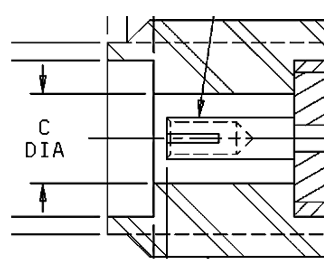
2.92 mm (K) Socket/Fe Interface Derived From MIL-STD-348 Figure 323-2 (MIL also refers to 2.92 mm as “SMK” for Subminiature type K)
As connector diameters become smaller, if production is done correctly, resultant connectors can operate at higher frequencies before moding. As connectors become smaller, they are subject to increased manufacturing and termination costs, plus damage from improper handling and mating. Successful application involves tradeoffs.
In a variation on the theme of Moore’s Law, one could say that a size reduction of a coax connector takes place every two years. Have we reached the limits of the coax connector? Can we build, handle, or terminate anything smaller than the 1 mm connector? Yes! The newest coax connectors in production include 0.8 mm and 0.6 mm. The 0.4 mm is under discussion for use/production by Anritsu.”
Design Notes:
Sizes Standard, miniature, and micro
Common coax connector types
- Standard: Type N and BNC standard connectors are discussed above. 7-16 DIN is a high power, Low PIM connectors, widely used in antenna systems and base stations supply better performances with regards to interference and intermodulation rejection. TNC connectors, sometimes referred to as Threaded BNC, with interface defined in MIL-STD-348, have 50-ohm impedance with some models operating to 11-12 GHz.
- Miniature: SMA (Subminiature Type A) connectors are used in microwave systems, hand-held radio and mobile telephone antennas and, more recently, with Wi-Fi antenna systems; SMB (Subminiature Type B) is smaller than SMA and features a push-on (snap-on) coupling and is available in 50 Ohm or 75 Ohm versions. FAKRA is a modified SMB connector with a keyed and color-coded plastic housing and latch, used in the automotive industry; SMC (Subminiature Type C) uses a threaded interface and is available in 50 ohm and 75 ohms.
- Microminiature Connectors: MCX is similar to the SMB with quick connect/disconnect, but smaller in size and lighter in weight with applications in telecommunications.
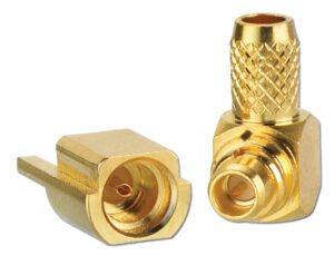
MMCX Connectors from Winchester Interconnect are available in non-magnetic, solderless, straight, right angle and easy snap for PCBs.
- Millimeter Wave Connectors: SMP (GPO) is a push-on, blind-mate connector that has a higher
- Millimeter Wave Connectors SMP (GPO) is a push-on, blind-mate connector that has a greater frequency range than the BMA (extended range up to 40 GHz) and can tolerate up to 0.010” radial and axial misalignment with minor VSWR change; SSMP (GPPO) is a smaller, lighter weight version of the SMP (GPO) with a frequency capability up to 65 GHz. An even smaller version termed SMP3 (or SMPS) is often used for 70 GHz although designed with a frequency cutoff above 90 GHz. 2.92 mm is compatible with SMA connectors and has a frequency capability of 40 GHz; 2.4 mm (50 GHz) looks similar to SMA but has a smaller, rugged interface, with a frequency capability of 50 GHz; 1.85 mm (for 65 GHz) is intermateable with the 2.4 mm, with a frequency capability of 65 GHz.
Mating: Plugs have a pin/male center and jacks (mating receptacles) have female/socket contacts. Reverse-sex versions also exist.
Fastening mechanisms: Thread, bayonet, braces, latching, and blind mate (detent).
Applications: Common types of RF connectors are used for television receivers, two-way radio, industrial and scientific measurements instruments, satellites, radar, Wi-Fi, and 5G “new radio frequencies.”
Suppliers (varying by connector series): Carlisle Interconnect Technologies, COAX Connectors, DigiKey Electronics, IMS Connector Systems, I-PEX, Molex, Radiall, SV Microwave, TE Connectivity, Samtec Inc., Smiths Interconnect, Winchester Interconnect, and others.
This article was developed with assistance from Richard Fiacco, Manager, Business Development for North America, IMS Connector Systems
Like this article? Check out our other Meet the Connector, circular connectors, and our Datacom and Telecom Industry Page, and our 2022 Article Archive.
Subscribe to our weekly e-newsletters, follow us on LinkedIn, Twitter, and Facebook, and check out our eBook archives for more applicable, expert-informed connectivity content.

- What is a Cable Tie? - July 28, 2026
- What is a MIL-DTL-28748 Connector? - July 21, 2026
- Omniball®: Reliable Connections for Challenging Designs - May 19, 2026