The Cabled Backplane Challenge
The Cabled Backplane Challenge
|
The advantage of a cabled backplane system is the capability to maintain signal integrity at 25Gb/s data rates and beyond, and at distances two to four times greater than a conventional backplane design. In addition, a variety of system configurations can be utilized to provide design flexibility to the interconnect manufacturer and OEM. The challenges of implementing a cabled backplane system design are:
Despite the challenges, the data rates and throughput achieved with a cabled backplane system is necessary to take us into the next generation of computational and information technology. |
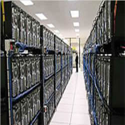
In the never-ending quest to achieve more and faster data, the traditional PCB backplane approach used in systems such as servers, switches, and routers has reached certain limitations in achieving maximum throughput. Data signal integrity at and beyond 25 Gb/s rates is compromised with traditional PCB materials and geometry. As these systems continue to achieve greater computational power, backplanes and the number of daughtercards they support become greater in size, number, and complexity.
As a result, the distances that the data must travel can become large enough that insertion losses can significantly degrade the signal. This has led many in the electronic manufacturing industry to look for an alternate means to achieve data rates and throughput that will take us into the next generation of information technology. One of these means involves the use of high-speed cable technology to connect the daughtercards, line cards, and switch cards in these various machines.
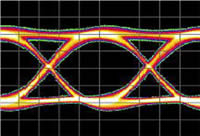
The advantages of using high-speed cable in these system applications are significant and may outweigh the inherent challenges. Obviously, the increase in data speed is the key advantage, with state-of-the-art data speeds currently at 25Gb/s and moving rapidly to 40Gb/s. Utilization of high-speed cable allows insertion loss, return loss, skew, cross-talk, and other signal integrity attributes to be maintained within OEM performance specifications at these higher speeds. Additionally, the reduced insertion loss achieved by the high-speed cable allows signal integrity to be maintained at distances two to four times greater than a conventional PCB backplane design. This is critical because it is possible to see data channels of three feet or more in full rack systems. In addition, many different design and board orientation configurations can be incorporated. These include a backplane or midplane, and a conventional or orthogonal orientation. The cabling lends itself to creative and optimized system designs.
 As in all aspects of life, the advantages are countered by the many challenges faced when implementing this technology. As mentioned, the larger systems typically require the cabled approach because of the greater data lengths involving a larger number of daughtercards, switch cards, etc. Each card will typically connect to all other cards in the system, resulting in many point-to-point connections. These connections are accomplished via a twinax cable with a differential pair configuration. Many mating cable headers and receptacles may be necessary along the edge of a daughtercard.
Complicated pin mapping schemes are needed to understand how each of the cables is routed from board to board. This requires close collaboration between the OEM and the interconnect solution manufacturer. With the possibility of thousands of point-to-point connections required in some systems, one can imagine the complexity of the cable routing. The routing can sometimes require challenging wire management involving multiple wire lengths and bends. How this impacts electrical and mechanical performance is of concern to the design engineer. Performance integrity before and after product verification testing must be ensured at the cable assembly level as well as the system level.
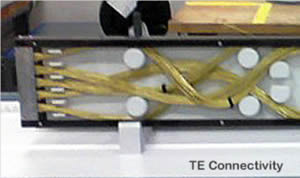 Also inherent in these larger systems with many point-to-point connections is the considerable amount of cable required. Some systems could consist of thousands of differential pair channels. It is not unreasonable to expect that thousands of feet of twinax cable will be required in a system configuration. As a result, additional weight is added to a cabled system as compared to the conventional backplane solution. This becomes a concern not only in packaging and transportation but is an important consideration in shock and vibration and other validation testing. Damage to these systems can be difficult to detect, especially after shipment from the manufacturer. Repair after installation can be one of the most challenging aspects of the cabled backplane system.
In a conventional PCB backplane configuration, the backplane itself assists in maintaining the structural integrity of the overall system. In the cabled solution, the PCB backplane is either completely or partially eliminated. Therefore, alternate means may be needed to achieve the structural integrity of the system, especially as system size grows. This can take the form of a sheet-metal structure and complementary fasteners to secure the header connectors and wire assemblies in their proper positions and registration. Alignment features are necessary to secure proper registration between the structure and the rack as well as the mounting of the header and receptacle on the edge of the mating daughtercard. It is essential the sheet-metal structure allow for float of the header connectors, which compensates for a stack-up of tolerances in the alignment hardware associated with the mating of cable headers to daughtercard. Finally, the metal structure must have sufficient strength to withstand the potentially significant mating forces required by multiple line card engagements. The designer must perform analysis and testing to minimize bowing or warping of the structure during mating, which can result in improper termination of the connector system.
Additionally, in order to ensure signal integrity at the 25+Gb/s speeds, termination of the high-speed cable to the connector must be accomplished while still maintaining the characteristic impedance, typically 85 or 100 ohms, of the overall system. Wire termination techniques commonly used are welding, which can be achieved by laser, ultrasonic, or resistance methods, or soldering. Termination of the differential signal wires and the ground wire or braid between the connector structure and the cable can be challenging. Manufacturing processes must be precise and monitored continuously to maintain quality and performance objectives.
All four leading high-performance backplane connector manufacturers are developing cabled backplane interconnect systems. The products range from cable assemblies to value-added structures with integrated cabled assemblies for mechanical support, registration, and alignment attributes.
 Amphenol TCS has been building cable backplane systems for years using its GbX backplane connectors. More recently, it has used its XCede connector family as the foundation of a value-added tray configuration to manage cable management.
FCI Electronics uses its ExaMAX backplane connector and 3M twinax cable to provide a cabled backplane solution. This allows for the termination of the cable to individual contact wafers. The connector/cable assembly is inserted into a cutout in the backplane and secured by a latching assembly applied from the front.
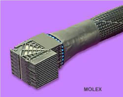
Molex has been building cable backplane assemblies using its UHDM, GbX, and Impact high-speed backplane connectors. Twinax cables are provided internally.
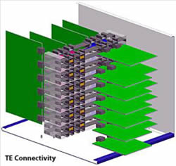 TE Connectivity has been building cable backplane assemblies and systems using its STRADA Whisper connector family. Discrete twinax cables are terminated to cable header connectors mounted into a complex sheet metal structure. This allows the connectors to float in three axes to compensate for tolerance stack-ups and also provides alignment for connector mating.
With the cabled system, interconnect manufacturers have the design flexibility to provide the OEM with a variety of system configurations. The backplane configuration with daughtercards mounted parallel to each other is certainly a popular approach. In addition, a midplane/orthogonal configuration mounts cards in a 90-degree orientation. Cabling in this manner typically connects the cards in the midplane space, allowing for more efficient thermal management. Improvements in electrical performance and signal integrity are enhanced utilizing cable in these various configurations.
The utilization of high-speed cable can undoubtedly improve electrical performance at 25Gb/s and beyond. Other than the use of fiber optic technology, the cabled approach at present is one of the few alternatives for the larger computing and switching machines.
Though the challenges are not insignificant, the rewards are great for those that can adapt with flexibility and innovation. Machines utilizing this technology can certainly provide a competitive edge in performance. As always, the key is achieving the quality, performance, and the cost-effectiveness necessary to successfully manufacture a product that moves beyond conventional means.
- State of the Industry: 2022-2023 Connector Sales - April 16, 2024
- Amphenol is On a Roll - April 2, 2024
- Nicomatic Proves That Two Heads are Better Than One - March 26, 2024
