What is an Ultra-High-Density Connector?
Ultra-high-density (UHD) connectors are specialized, compact interconnects designed to pack a maximum number of signal or power contacts into a minimal footprint, typically to save space without compromising performance. They feature a low profile, a high pin count, fine pitch, and, often, enhanced EMI shielding. These connectors are crucial for reducing PCB size and supporting increased signal speeds. The fine-pitch spacing enables high-speed data transfer in data centers, aerospace, robotics, and other high-performance applications.
The development of UHD connectors evolved in response to the ongoing demand for smaller, faster, and more efficient electronic systems. Data requirements continue to increase, devices are shrinking, and more capabilities are required in the same amount of space. Therefore, the “density” of a connector (the number of contacts per square inch) has become a primary engineering metric.
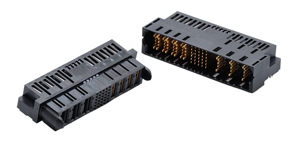
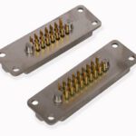
Amphenol’s PwrBlade ULTRA HD+ connector series features an enhanced high-power contact design capable of providing up to 100A per contact (per 4 adjacent contacts) and high-density signal options with up to 6 signal pins per column. The connector series features Amphenol’s proprietary silver-based plating technology GCS which ensures best-in-class current carrying capability and ultra-low end-of-life contact resistance of 0.4mΩ max. Compared to the earlier PwrBlade series designs, PwrBlade ULTRA HD+ maintains a low profile of 11.40 mm height above the board that enables airflow for efficient system cooling. The modular tooling design permits versatility for a wide range of applications ideal for power supply units (PSUs), power distribution boards (PDBs), and other high-current applications.
In the 1980s and 1990s, the rise of portable computing and advanced avionics drove the need for smaller, space-saving components. The first solution was reducing pitch (the distance between the centers of adjacent contacts) from the standard 2.54 mm to 1.27 mm, and eventually to submillimeter (0.5 mm or 0.4 mm) pitches. The space previously allotted for dozens of signals now accommodates hundreds. Military and Aerospace requirements also influenced the change as the need for lightweight, vibration-resistant, high-pin count connectors in fighter jets and satellites increased. This led to the development of high-density micro and nano connectors.
As traditional machined pins reached a physical limit and became too fragile, changes in pin construction became necessary. Traditional pins were replaced with stamped-and-formed contacts that allow for tighter tolerances and mass production at a smaller scale, and blade-and-beam systems that provide more surface area for electrical contact while maintaining a slim profile.
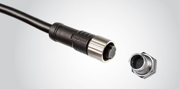
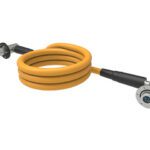
ALTW UHD X-Lok Push-Lock Connector are compact push-lock interconnects designed to deliver high pin count and reliable data transmission in space-constrained applications. With up to 33 contacts in a mini-size form factor, UHD X-Lok connectors serve as an alternative to traditional circular connectors such as M12 while increasing signal density.
As copper reached its bandwidth limits due to crosstalk and electromagnetic interference (EMI), development shifted toward optics with MT ferrules and multi-fiber alignment.
The ongoing evolution of UHD connectors is currently driven by data centers and AI, medical robotics, and e-Mobility and battery management.
UHD challenges
The main challenges of UHD connectors are:
- Signal integrity and crosstalk
As contact pitch decreases, the risk of EMI increases.
- Differential pair routing. Consistent impedance across the connector is vital.
- Crosstalk mitigation. Integrated grounding planes or “shielded row” architectures prevent signal leakage between pins.
- Thermal management
High density usually means a higher concentration of power. Even low-current signals generate cumulative heat when hundreds of pins are active simultaneously.
- Derating curves. It is critical to check the current-carrying capacity when all pins are loaded versus a single pin.
- Airflow obstruction. UHD connectors can act as physical “walls” on a PCB, potentially blocking airflow to hot components like FPGAs or processors.
- Mechanical constraints and ruggedness
The smaller the pins, the more fragile they become.
- Mating alignment. UHD connectors often require blind-mating features or robust alignment housings to prevent bent pins during manual assembly.
- Extraction force. The cumulative force required to mate or unmate a 400-pin connector can be significant, potentially stressing the PCB solder joints.
- Manufacturing cost. Pitches smaller than 0.5 mm significantly increase PCB fabrication costs and require tighter tolerances for surface mount technology (SMT) placement.
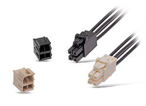
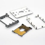
Molex Ultra-Fit Power Connectors from Heilind eliminate same-circuit-size cross mating, optimize space savings, and reduce terminal back-out. Color-coded housings mitigate the risk of mis-mating. The streamlined design is 17% smaller than competing power connectors providing space savings and an ultra-low mating force that reduces operator fatigue when mating numerous high-circuit connectors.
- Termination styles
The method of attaching the connector to the board impacts performance and repairability.
- SMT offers the best signal integrity but has less mechanical “grip” on the board.
- Press-fit avoids heat-cycling the board in backplane applications but requires thick PCBs and specific insertion tooling.
- BGA (ball grid array) mezzanine allows for the highest density but requires X-ray inspection to verify solder joints.
- Fiber Optic Alternatives
In some ultra-high-density scenarios, copper reaches its physical limit due to heat and EMI.
- Multi-fiber push-on (MPO). For data-heavy applications, moving to multi-fiber ferrules (like MT ferrules) can provide higher bandwidth density than copper without the weight or interference issues.
COMPARISON TABLE: HIGH-DENSITY TRADE-OFFS
| Feature | SMT Termination | Press-Fit Termination |
| Space Efficiency | Excellent (Top layer only) | Good (Requires thru-holes) |
| Signal Speed | Very High | High |
| Mechanical Strength | Moderate | Very High |
| Repairability | Challenging | Easier (with tooling) |
CONNECTOR CONFIGURATIONS
| Common Types of UHD Connectors | ||
| Type | Application | Key Feature |
| Micro-Mezzanine | Printed Circuit Boards (PCBs) | Connects two parallel boards with hundreds of points in a tiny stack height. |
| Multi-Fiber (MPO/MTP) | Fiber Optics | Aligns up to 72 fibers in a single rectangular ferrule for data center backbones. |
| High-Density Circular | Aerospace/Military | Uses “nano” contacts to fit 50+ pins into a connector the size of a thumbnail. |
Contact Configurations
- Reduced pitch.5 mm, 0.4 mm, or even smaller compared to traditional pitch of 2.54 mm.
- Multi-row architecture. Staggered, multi-row grids replace a single row of pins to utilize vertical and horizontal space effectively.
TECHNICAL SPECIFICATIONS
| IDENTIFICATION | |
| Product / Series Name | Ultra-High-Density (UHD) connectors, high-density array, micro-D connectors, high-density PCB connectors. Specific series names include ALTW Ultra-High Density (UHD) X-Lok, Samtec AcceleRate® HD, Amphenol PwrBlade, ODU AMC |
| Manufacturer(s) | Amphenol Communications Solutions, Amphenol LTW, Samtec, TE Connectivity |
| Industry Category | High-density array (board-to-board), high-density fiber optic, Micro-D and Nano-D, high-density D-Sub |
| Relevant Standards | Standards focused on signal integrity, harsh environments, and high-speed performance (64 Gb/s+) such as IEC 60320 for power and PCIe 6.0/CXL 3.2 compliance for rigorous speed/data density specifications. |
| MECHANICAL SPECIFICATIONS | |
| Shell / Housing Shape | Rectangular (board-to-board); Circular (scoop-proof) |
| Shell Material(s) | Aluminum alloy is the standard for aerospace, while stainless steel or titanium is used for harsh environments or medical sterilization. High-grade thermoplastics (like PEEK or LCP) are used for weight-sensitive or non-conductive requirements. |
| Shell Finish / Plating | Electroless Nickel (for conductivity and wear), Black Zinc Nickel (for non-reflective, RoHS-compliant corrosion resistance), and Gold (for high-end medical or space applications). |
| Overall Dimensions | Vary widely depending on pitch count |
| Mounting Type(s) | PCB Mount: Through-hole, SMT, or Press-fit. Panel Mount: Jam nut or square flange. |
| Plug Types | Straight cable plugs, right-angle plugs, and “floating” blind-mate plugs designed to correct for misalignment in rack-and-panel systems. |
| Receptacle Mounting Styles | Front-mount or rear-mount (jam nut), and board-to-board “mezzanine” styles for vertical stacking. |
| Mating Cycles (rated) | 500-5,000 cycles |
| Locking Mechanism | Push-pull, breakaway |
| Keying / Anti-mismating | Physical “keys” (tabs and grooves) or visual color-coding. In UHD circulars, multiple clocking positions (e.g., N, A, B, C, D) |
| Weight (typical) | 2-15 Grams |
| CONTACT SPECIFICATIONS | |
| Contact Pitch | 0.5 mm, 0.4 mm |
| Contact Material | Beryllium Copper (BeCu); Copper alloys (including phosphor bronze) |
| Contact Plating | Gold over nickel; silver-based GCS |
| Termination Method(s) | Crimping; SMT; mechanical splicing |
| Current Rating (per contact) | 0.5A to over 30A per contact |
| Voltage Rating (working) | Typically 100V AC/DC-300V AC/DC; can be up to 600V–3000V DC |
| SEALING & ENVIRONMENTAL | |
| IP Rating | IP67, IP68, and IP69K (for medical) |
| Sealing Type | Interfacial seals, O-rings, and hermetic sealing may be used |
| Seal Material | Fluorosilicone, Viton (FKM), silicone |
| Operating Temperature Range | Typically -55 °C to +125 °C; for some applications may exceed 200 °C. |
| Shock Resistance | Often tested at 50g or 100g |
| EMI / RFI Shielding | Due to the reduced pitch, advanced shielding is required |
| MATERIALS | |
| Plug Insulator Material | LCP, PEEK, PPS |
| Receptacle Insulator Material | LCP, PEEK, PPS, Polyamide |
| Overmold / Backshell Material | Overmold: TPU, PVC, Silicones, PEI, LCP, aluminum/stainless steel |
| RoHS / REACH Compliance | Yes – from most major manufacturers |
| Halogen Free | Depends on the specific product and materials |
| UL Flammability Rating | UL94 V-0 is most common |
| ELECTRICAL PERFORMANCE | |
| Impedance (if controlled) | Designed to match standard system requirements, typically 50 Ω for single-ended signals or 100 Ω for differential pairs. As density increases, maintaining this impedance becomes a significant challenge. |
| Data Rate / Bandwidth | Currently pushing into the territory of 112 Gb/s and 224 Gb/s per lane. |
| EMI Filter Integrated | Depends on the application |
| TESTING & COMPLIANCE | |
| Testing Standards Referenced | EIA-364; IEEE 802.3 (Ethernet) & OIF, IEC 60512-25, IEC 60068, application specific standards |
Suppliers
Amphenol Communications Solutions, Amphenol LTW, Samtec, TE Connectivity, Corning, CommScope, Glenair, LEMO, ODU, US Conec
Markets & applications
Datacom/Telecom, Automotive, Industrial, Military and Aerospace, Medical, Consumer
Data centers and cloud computing, AI infrastructure, storage systems, networking; 5G and 6 G base stations and routers, edge computing; EV battery management systems (BMS), and thermal management; ADAS and autonomous driving, SDV (software-defined vehicles); industrial automation, robotics, IIoT sensors; navigation systems and satellite components; portable diagnostic tools, wearable health monitors, and surgical robotics; handheld devices and test equipment.
Related products
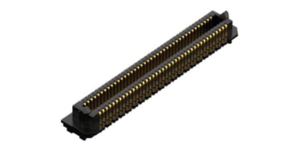
AcceleRate® HD features high-speed Edge Rate® contacts are designed for high-speed, high-cycle applications and are optimized for signal integrity performance. Up to 400 total I/Os make these connectors incredibly dense, while maintaining a low profile with 5 mm to 16 mm stack heights. The open-pin-field design offers maximum grounding and routing flexibility. The surface of the contact is milled creating a smooth mating surface, which reduces wear on the contact increasing durability and cycle life. Lower insertion and withdrawal forces allow zippered unmating. AcceleRate supports 64 Gb/s PAM4 (32 Gb/s NRZ) applications and is PCIe® 6.0/CXL® 3.2 capable.
Like this article? Check out our other Meet the Connector and Connector Basics articles, our Connector & Cable Special Topics Market Page, and our 2026 Article Archives.
Subscribe to our weekly e-newsletters, follow us on LinkedIn, Twitter, and Facebook, and check out our eBook archives for more applicable, expert-informed connectivity content.
- Extreme Temperature Innovations for Aerospace and Defense - July 21, 2026
- Connectors for Soldier Systems Product Roundup - July 21, 2026
- July 2026 Connector Industry News - July 21, 2026