Board-to-Board Connectors in Harsh Environments
As reliable interfaces between PCBs, board-to-board connectors increasingly perform in harsh environments, where they fulfill mechanical functions as well as transmit signal and power connectivity. That makes it crucial to specify the right component for the conditions.

Figure 1: Board-to-board connectors act as reliable interfaces between PCBs, fulfilling mechanical, signal, and power-related functions.
Article contributed by Detlef E. Preissler, Senior Specialist, Product Marketing Board-to-Board Connectors, Phoenix Contact GmbH & Co. KG, Blomberg, Germany; and Devin McMahon, Product Marketing Specialist – Connectivity, Phoenix Contact USA, Middletown, Pa.
Process engineering, automation networks, transportation logistics, information technology, medical technology, and other electronic systems and equipment increasingly operates in harsh environmental conditions. Board-to-board connectors play a key role in these applications. As high-density interfaces between PCBs, they provide reliable signal and power (Figure 1), and to perform in harsh environments, these connectors must be ruggedized.
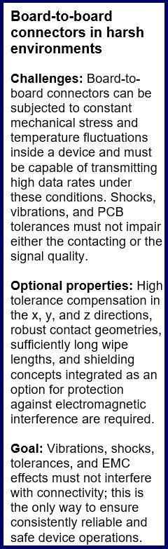
Many industrial applications operate under harsh ambient conditions. Energy extraction and generation industries depend on a wide range of vehicles, machinery, and devices that operate for long periods of time, often autonomously, in the full range of environmental conditions. This equipment endures moisture, dust and particulates, temperature extremes, and shock and vibration. Each piece of equipment is in communication with the others, using data exchanges to perform successful operations together. Additional equipment may include drones with cameras and sensors to monitor and inspect technical facilities and properties, such as wind turbines or offshore oil rigs. The mechanical and thermal stresses on the electronics inside these machines must be designed to resist harsh environments and prevent contact failure.
The process and automation sector may take place in indoor facilities, but it too depends on the reliable operation of synchronized motors, machines, conveyor systems, and robots, all of which can generate shocks and vibrations. Indoor conditions can also be harsh environments and must be designed using ruggedized connectors and other components.
Medical equipment is also exposed to harsh environment conditions. For example, mobile medical devices used in clinical and home settings are often subjected to shocks and vibrations. Like other harsh environment applications, trouble-free operation is essential. If a defibrillator falls to the ground during use, it must still be able to function — ruggedized components protect lives. Infusion and monitoring devices used in mobile settings, motorized hospital beds and stretchers, to ambulance and helicopter deployments – are constantly exposed to shocks and vibrations, yet they must function reliably.
Impact on the connector
To specify high-reliability, ruggedized, or heavy-duty connectors, important factors to consider include the IP rating, connector durability, strain relief, and vibration and shock resistance. The components built into the device should be considered carefully as well. Internal components like board-to-board (BTB) connectors cannot provide visual feedback on their status during operation. They also have tolerance-absorbing properties in very tight installation spaces. To function reliably, devices must be designed with board-to-board connectors that can be trusted to maintain a secure connection even under stress.
Board-to-board connectors in harsh environments
BTB connectors must transmit high data rates, withstand mechanical stress, compensate for tolerances, be space-efficient, and operate reliably in harsh environments. While corrosive environmental factors such as moisture, dust, chemicals, and UV radiation can largely be disregarded inside a device with a rugged housing design, factors such as temperature fluctuations and mechanical stress impact internal components.
As data rates increase in applications that facilitate the real-time transmission of image, video, and measurement data, an additional challenge arises. These applications require special protection against electromagnetic interference (EMC). Potential interference is generated by high-speed signals within the connector and operating environment, and EMC interference can affect the connector’s signal paths (Figure 2).
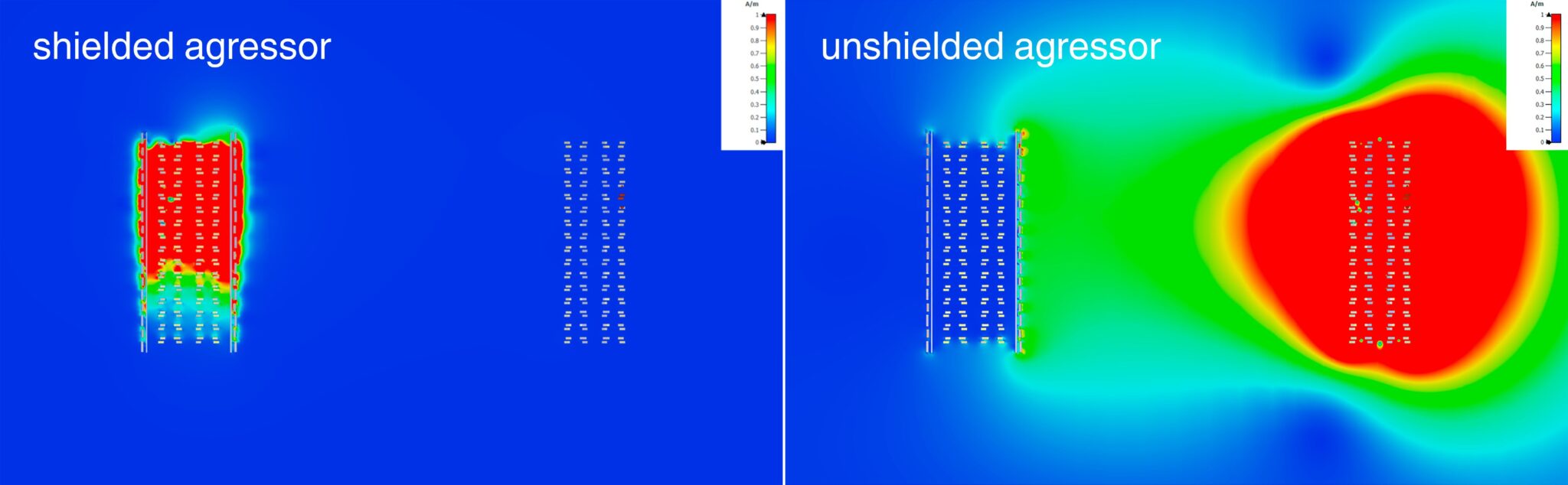
Figure 2: FP 0,8 has excellent shielding properties (EMC protection).
Many BTB connectors on the market are optimized for specific applications. However, a robust, flexible, and compact BTB connector system can address multiple challenges. (Figure 3)
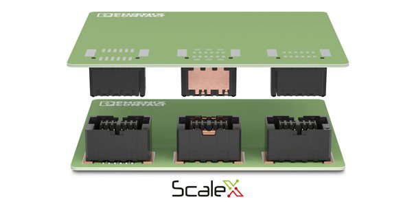
Figure 3: Flexibility with three compatible versions in the FP 0,8 series: AOI, SH, and SL.
For challenging environments, an ideal BTB connector family features a wide range of combinations, including automated optical inspection (AOI) and layout-compatible shielded (SH) and unshielded (SL) versions. Stack heights from 6 mm to 21 mm, with optional shielding, fit a wide range of applications.
Building a connector for harsh environments
In principle, robustness begins with the initial joining or blind plugging of the BTB connectors. During this process, the contacts may not become damaged. The connector housing design must make it easy to identify and correctly position mating connectors during connection. (Figure 4)
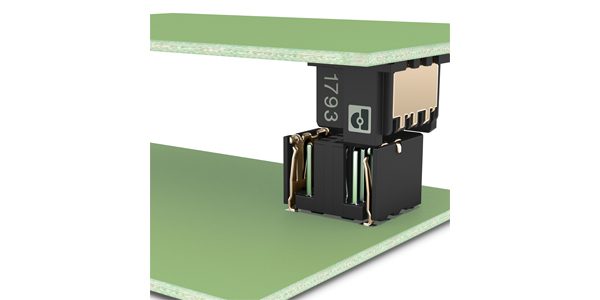
Figure 4: FP 0,8 allows robust insertion with high tolerance compensation.
For contact reliability, a double-contact system (two contact points) generally offers advantages over a single-contact system (single-beam/one contact point). In addition to the standard double-contact design, which encloses a pin contact (male) like a pair of tweezers (female), some connector systems include an additional pin contact.
In combination with the robust housing geometry, this version of a double contact even compensates for x-y-z tolerances when mated, even though it is not a traditional floating connector. This results in a tolerance compensation of at least +/-0.3 mm in the x-y direction and a wipe length of 1.5 mm in the plug-in direction (z direction). If the entire wipe length is used, a comfortable residual contact overlap of 0.8 mm remains. (Figure 5)
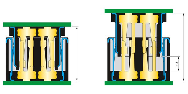
Figure 5: FP 0,8 has a large wipe length of 1.5 mm.
These BTB connectors can compensate for misalignment of up to ±5° between the PCBs they connect, so they do not compromise the connector’s reliable contact. Due to thermal and mechanical stresses in harsh environments, the position of the PCBs relative to one another may change even during operation. In the range stated above, these BTB connectors ensure a reliable electrical connection. (Figure 6)
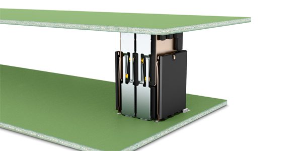
Figure 6: The FP 0,8 double contact enables a variable wipe length of 1.5 mm, with a residual contact overlap of 0.8 mm.Selected gold plating on the contacts can ensure a lifespan of 500 mating cycles. In addition, it has a positive effect on contact reliability against shock and vibration. A connector system specified in accordance with key standards, such as IEC 60512 and certified for vibration and shock tests in accordance with IEC 61373 (Cat 1 and Cat 2), will further ensure reliability.
While the connector can largely compensate for mechanical factors, what about electromagnetic interference? Optional shielding can be a solution here.
Figure 3 shows three types of BTB connectors. The AOI version is the classic, unshielded model. In this version, the solder joints are routed outward to the sides, similar to a small outline (SO) housing used in semiconductor technology. In the SL versions, the PCB layout is more in the form of a land grid array (LGA), whereas the shield connection in the SH version has an SO character. To optimize shielding performance, as many shield connections (solder joints) as practical were put in place. (Figure 7)
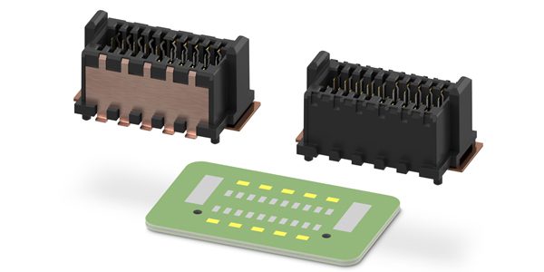
Figure 7: FP 0,8 has compatible PCB layouts for the SH and SL versions.
With this optimized shielding technology, both the high-speed data and signals in the connector and the connector’s external environment are protected against ESD effects. The modular design of the SH and SL versions means developers can start with the SH layout and decide later whether to continue using the shielded (SH) or unshielded (SL) version. In addition, the electrical isolation of the two metal shields allows a power supply to be routed through the shields, turning the connector into a hybrid BTB connector. This is a clear simplification for the design-in process.
BTB connectors play a key role in harsh environment electronics. New options offer the durability needed to withstand mechanical, thermal, and electromagnetic stresses while providing the flexibility, compact design, and performance needed by advanced systems.
Visit Phoenix Contact to learn more.
Like this article? Check out our other Autonomous Vehicles, Board-to-Board and Harsh Environment articles, our Industrial Market Page, and our 2026 Article Archives.
Subscribe to our weekly e-newsletters, follow us on LinkedIn, Twitter, and Facebook, and check out our eBook archives for more applicable, expert-informed connectivity content.

- A Five-Layer Clad Solution for High-Performance Battery Interconnects - October 6, 2026
- High Voltage Interlock for Commercial Vehicles: A Must-Have or a Nice to Have? - September 29, 2026
- Case Study: A Partnership to Improve Rail Health - September 29, 2026