What is an Adhesive Mount Antenna?
An adhesive mount antenna is a low-profile external antenna that is attached to a surface using a pressure-sensitive adhesive backing, typically a foam tape. Available in single-band and multiband configurations covering cellular (2G through 5G), GNSS, Wi-Fi, Bluetooth, and combinations, adhesive mount antennas are commonly used for vehicle telematics, fleet tracking, IoT gateways, and asset monitoring applications.
Origin & development
Adhesive mount antennas emerged in the 1990s alongside the growth of cellular tracking and telematics applications as a lower-cost, drill-free alternative to through-hole NMO and stud-mount antennas. They are widely used for vehicles and equipment with plastic, composite, or glass surfaces. They gained wide adoption in the 2000s for GSM-based asset tracking and expanded with the growth of LTE-M, NB-IoT, 5G, and multiband combination antennas that consolidate capabilities into a single low-profile housing. This mounting type is commonly used with PIFA (planar inverted-F antenna) and patch or microstrip form factors with a low overall height (typically 5–25 mm) that allows the antenna and its cable to be routed flat against a surface.
Ground plane independence
A key design variable is whether the antenna requires an external ground plane. Quarter-wave monopole and T-bar dipole designs are ground-plane dependent: a conductive surface beneath them acts as an RF reflector that completes the antenna circuit. When mounted on non-metallic surfaces, these designs require an adhesive-backed aluminum or copper foil ground plane beneath the antenna, sized to at least ¼ wavelength at the lowest operating frequency.
PIFA and patch designs are ground-plane independent: they incorporate an integral ground plane within the antenna housing. Ground-plane independent designs now dominate the vehicle telematics and IoT markets because fleet vehicles increasingly use non-metallic body panels.
Variants & form factors
- I-Bar: Cylindrical or oval low-profile housing, typically 100–150 mm long × 20–25 mm diameter, mounted horizontally on its flat back. Houses a PIFA or dipole element in an IP67 or IP69 radome. The dominant cellular telematics form factor; offered in single-band and multiband versions.
- T-Bar: Flat dipole element in a thin rectangular housing, mounted adhesively to a flat surface with the feedline exiting from the center. Very low profile (2–4 mm height); commonly used for GSM/cellular inside vehicle cabins.
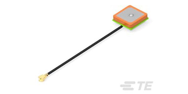
- Puck/Patch: Circular or square low-profile housing, 40–100 mm diameter, 10–20 mm height, housing a patch or active patch element. Predominant form for GNSS-only and combination GPS+cellular units; integral ground plane standard.
- Combination (multi-technology): Single housing combining two or more antenna elements — e.g., 2×LTE MIMO + GNSS + Wi-Fi (up to 6-in-1). Increasingly the default choice for IoT gateways and connected vehicle platforms to minimize installation points.
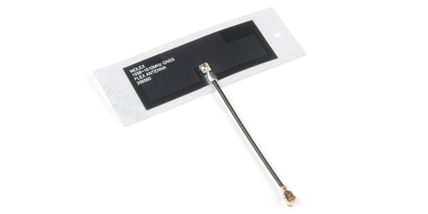
- Film/Flexible: Ultra-thin printed antenna on a flexible substrate, for conformal mounting on curved glass or plastic (e.g., windshield DAB antennas). Typically narrow-band; predominantly used in automotive OEM infotainment.
Mounting
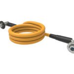
The adhesive layer is typically acrylic foam tape chosen for its UV resistance, temperature cycling tolerance, and strength on surfaces. To attach the antenna, the tape’s liner is peeled and the antenna is pressed firmly onto the surface. Once bonded, removal typically requires a cutting tool and risks finish damage. The RF output is a coaxial cable tail (most commonly RG-174, RG-178, RG-58, or low-loss KSR-200P/LMR-100 equivalents) terminated in SMA, N-type, FAKRA, TNC, or FME connectors. depending on the equipment interface. Standard cable lengths are 1.5 m, 3 m, and 5 m; custom lengths are available from most manufacturers. For ground-plane-dependent designs on non-metallic surfaces, a conductive foil ground plane (minimum ¼λ diameter at the lowest operating frequency, typically 70–150 mm for cellular) must be bonded beneath the antenna base.
Markets & applications
Automotive, Transportation
Vehicle telematics and fleet management (commercial trucks, vans, buses, rail); asset tracking; IoT gateway and router hardware; public safety and first-responder vehicles; marine vessels; utility metering and smart grid edge devices; and industrial automation enclosures
TECHNICAL SPECIFICATIONS
| IDENTIFICATION | |
| Industry Category | External Antenna — Cellular, GNSS, Wi-Fi/Bluetooth, ISM, Combination/Multiband |
| Antenna Type / Technology | PIFA (most common for cellular); Patch/microstrip (GNSS, combination); Dipole/quarter-wave monopole (T-bar, I-bar wideband); Active patch with LNA (GNSS). |
| RF PERFORMANCE | |
| Frequency Band(s) | Cellular: 698–960 MHz (low band), 1710–2700 MHz (mid band), 3300–3800 MHz (n77/n78 5G); GNSS: GPS/GLONASS 1575/1602 MHz; Wi-Fi: 2400–2500 MHz / 4900–5925 MHz; Bluetooth/Zigbee: 2400–2485 MHz |
| Frequency Range | Single-band cellular: 698–960 MHz or 1710–2700 MHz; Wideband cellular: 698–3800 MHz; GNSS: 1559–1610 MHz; Wi-Fi: 2400–2500 / 4900–5925 MHz |
| VSWR (max) | ≤2.0:1 across operating band for quality commercial products; ≤3.0:1 acceptable minimum per industry convention (2J Antennas, MobileMark); at 50 Ω reference impedance |
| Radiation Pattern ★ | Cellular/Wi-Fi (PIFA/dipole): Omnidirectional in azimuth, toroidal (doughnut); GNSS (patch): Hemispherical, broadside (peak gain toward zenith); Combination: per-element patterns as above |
| Impedance | 50 Ω (universal standard for cellular, Wi-Fi, GNSS, and ISM band systems) |
| Maximum Input Power | Passive antennas: 10–50 W continuous (50 W typical for cellular I-bar/T-bar); active GNSS: determined by LNA rating, not transmit power |
| PHYSICAL & MOUNTING | |
| Antenna Form Factor | I-Bar (cylindrical/oval low profile); T-Bar (flat dipole); Puck/Patch (circular or square); Film/Flexible (ultra-thin conformal); Combination (multi-element single housing) |
| Mounting Method | Industrial-grade pressure-sensitive adhesive (PSA) foam tape. Permanent bond; not designed for removal. |
| Connector Interface | SMA male (most common for IoT/telematics); SMA female; N-type male; TNC male; FME; FAKRA (automotive OEM); RP-SMA (Wi-Fi); U.FL/IPEX (internal board connection via pigtail). Specified at cable end, not antenna body. |
| Cable (if supplied) | Supplied as cable assembly. Typical: RG-174 (50 Ω, flexible, lossy over 1 GHz), RG-178 (smaller diameter), RG-58 (50 Ω, lower loss), KSR-200P / LMR-100 equivalent (low-loss for longer runs). Standard lengths: 1.5 m, 3 m, 5 m; custom on request. |
| Ground Plane Requirement | Ground-plane independent (PIFA/patch designs): No external ground plane required; operates on metal, plastic, glass, or composite. Ground-plane dependent (monopole/dipole designs): conductive surface min. ¼λ diameter at lowest frequency (e.g., ~75 mm for 1 GHz; ~105 mm for 698 MHz). Conductive foil tape acceptable substitute on non-metallic surfaces. |
| ENVIRONMENTAL & INGRESS | |
| Operating Temperature Range | −40 °C to +85 °C (standard commercial/automotive) |
| IP / Ingress Rating | IP67 (standard for most external adhesive mount antennas); IP68 or IP69 for heavy-duty and automotive-grade products |
| UV / Weather Resistance | Radome: UV-stabilized ASA, ABS, or polycarbonate. Adhesive: automotive-approved acrylic foam rated for outdoor UV exposure. Premium products (e.g., 2J Antennas polycarbonate/ASA) explicitly qualified for harsh outdoor environments including moisture, heat cycling, and debris exposure. |
| Vibration & Shock | Automotive-grade products qualified to ISO 16750 (road vehicles — electrical equipment); MIL-STD-810 testing offered by select manufacturers. Adhesive bond strength is the primary mechanical reliability concern. |
| MATERIALS | |
| Radome / Housing Material | ASA (acrylic-styrene-acrylate) or ABS most common; polycarbonate for high-impact applications; fiberglass for film antennas. UV stabilization standard for outdoor grades. |
| ACTIVE ANTENNA / LNA (GNSS elements only) | |
| Active / Passive | GNSS element: Active (integral LNA). Cellular and Wi-Fi elements in combination antennas: Passive. |
| LNA Gain | 23–28 dB typical at GNSS frequencies (GPS L1 1575.42 MHz; GLONASS 1598–1610 MHz) |
| Noise Figure | 1.0–1.5 dB typical for quality GNSS LNA |
| Supply Voltage (bias) | 1.5–5.5 V DC via coaxial DC bias injection (phantom power on center conductor). 2.7–5.5 V most common; 3.3 V and 5 V standard receiver outputs accepted. |
| Current Consumption | 15–40 mA typical; 25–30 mA at 3 V or 5 V most common. See 2J Antennas 2J6041PGFa (28 dB gain, 40 mA at 3 V) and 2J9607 series (23 dB at 3 V, 15 mA) for representative values. |
Suppliers
Manufacturers: Molex; TE Connectivity
Distributors: Mouser Electronics; DigiKey; TTI Inc.
Related Products
SMA Connector: Most common output connector on adhesive mount antenna cable assemblies
N-Type Connector: Used on higher-power or outdoor-grade antenna cable assemblies
FAKRA Connector: Automotive-standard RF connector used on telematics antenna leads
Like this article? Check out our other Meet the Connector and Connector Basics articles, our Senors & Antennas Market Page, and our 2026 Article Archives.
Subscribe to our weekly e-newsletters, follow us on LinkedIn, Twitter, and Facebook, and check out our eBook archives for more applicable, expert-informed connectivity content.
- EU Battery Regulation Prompts Design Changes for Battery Connectors - July 14, 2026
- What is an LGA Socket? - June 30, 2026
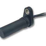
- What is a Speed Sensor? - June 23, 2026