Power Contacts/Connectors Part III – Current Rating 2
Power Contacts/Connectors
Part III: Current Rating 2
This week, let’s examine the current rating test program, which includes the measurements to be made and the conditioning and exposures to be applied in connector testing. Figure 1 includes an example program. A program of this general nature is under consideration in ECA CE-2.0 National Connector and Socket Standards.
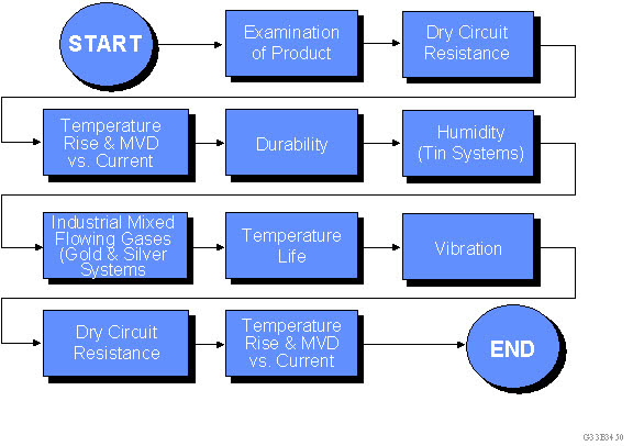 Figure 1: Representative current rating qualification test program.
Consider first the measurements to be made. The program begins with a dry circuit resistance, or Low Level Circuit Resistance (LLCR) measurement. The open circuit voltage is controlled at either 20 or 50 millivolts, with 20 being the recommended value. This dry circuit, or low level, voltage is too low to disrupt any films that may be present on the contacts. This measurement sets the baseline for the change in contact resistance, ΔR, to be determined at the end of the test program. The T-rise measurement is performed next, as described in the previous article. The typical current rating program will determine the current that causes a 30-degree Celsius T-rise, which, if the test is completed successfully, will become the current rating of the contact. If desired, a MilliVolt Drop (MVD) measurement is performed. The MVD is measured at the rated current.
These measurements are repeated, in the same order, at the end of the test program. It is important to do LLCR prior to T-rise or MVD because those measurements are done without voltage control, and the applied voltage may disrupt any surface films produced during the testing program, negating the intended effects of the conditioning exposures. If the measured ΔR meets the specification requirement, and the T-rise measurement at rated current is acceptable, the current rating of the contact is validated.
Now consider conditioning and exposures. For the purposes of this discussion, conditioning refers to a process which increases the susceptibility of a connector to degradation, while an exposure potentially causes degradation to occur. Durability and Temperature Life are conditioning processes, and corrosion and vibration are exposures.
The first step is durability in the mating and unmating of the connectors. Durability is intended to condition the contact finish to the desired state, End Of Life (EOL) or an intermediate state. Selection of the number of mating cycles was discussed in the previous article. This conditioning provides the potential for wear of the contact finish and an increase in the susceptibility of the contact to corrosion.
The second boxes relate to corrosion. Two different exposures are included, one for connectors using a tin finish, and one for noble metal (gold or palladium alloy) or silver contact finishes. The degradation mechanisms, and thus the exposures, are different for these systems. The primary degradation mechanism for tin finishes is fretting corrosion, or micromotion-stimulated oxidation of the tin contact interface, as discussed in earlier articles. For noble metal and silver finishes, copper and silver corrosion, through sulfur and chlorine reactions, are dominant. The environments and durations of the exposures are selected to be representative of the desired application qualification.
Next we’ll look at Temperature Life, or heat age conditioning. Temperature Life is intended to simulate the effects of stress relaxation on the contact normal force that will occur over the time/temperature profile of the intended application. An elevated temperature exposure for a shorter time can simulate the intended product life at the application temperature.
The final exposure is vibration; again, the details of the exposure are dependent on the intended application of the connector. The purpose of the vibration is to test the mechanical stability of the contact interface against disturbance forces. Alternative mechanical stability exposures include mechanical and thermal shock.
There has been extensive discussion over the years concerning the choice of conditioning and exposures (type, intensity, and duration) and their order in the test program. The following discussion provides the rationalization for the order of the steps in this program. The details and choices of the conditioning steps are outside the scope of this discussion.
The initial LLCR measurement validates that the contact interface is initially in an acceptable condition. The conditioning is intended to drive mechanisms that could lead to degradation of the contact interface. It is known that the major degradation mechanism for connectors is corrosion related. The conditioning and exposure order in this program recognizes that fact.
One of the major functions of the contact finish is to provide corrosion protection for the underlying base metals of the contact springs, usually copper alloys which are susceptible to sulfur and chloride corrosion, as noted earlier. Durability is intended to take contact finish to its intended final condition, EOL or otherwise. If wear-through of the contact finish occurs due to durability, the corrosion resistance of the contact will be impaired.
After this potential “degradation” of the contact interface, the contacts are subjected to the appropriate corrosion environment. If an unacceptable degradation of the corrosion resistance of the contact finish has occurred, corrosion products can be expected to form at or around the contact interface. Such corrosion products may not affect the contact resistance at this point, but if they are able, in some way, to get into the contact interface, an increase in contact resistance is likely. The next two steps are intended to exercise the potential for such corrosion product movement.
If the contact interface itself does not move, that is, if it is mechanically stable against the driving forces for interface motion in the application environment, corrosion products or contaminants around the contact interface are not likely to make their way into the interface. The mechanical stability of the contact interface is realized primarily by the friction created at the interface by the contact normal force. Stress relaxation, due to the Temperature Life exposure, will result in a decrease in the contact normal force, and therefore, a reduction in the mechanical stability of the interface. The reduction in contact normal force due to stress relaxation does not directly result in an increase in contact resistance; motion of the interface is required to cause an increase.
Creating the opportunity for such a motion is the intent of the final exposure, vibration. The mechanical stresses created at the contact interface during vibration provide the driving forces for interface motion and subsequent increases in contact resistance as a result of motion. Vibration is both a conditioning and an exposure. It is a conditioning step in that if motion of the contact interface occurs, additional wear of the contact finish can result. It is an exposure in the sense that it drives the motion that causes the contact resistance to increase by transporting corrosion products into the contact interface.
In summary, the rationale for this particular order of steps is:
- Durability-induced wear increases the susceptibility of the contact to corrosion.
- The corrosion exposures will lead to corrosion if sufficient degradation of the contact finish has occurred. Corrosion can occur directly at the interface, with an immediate increase in resistance, or around the interface, where it sets up a potential for motion-induced increases in resistance.
- Temperature Life decreases the contact force and increases the susceptibility of the contact interface to motion.
- Vibration increases the potential for motion and can bring corrosion products or contaminants around the contact interface into the interface, with resulting increases in contact resistance.
Note that each of these steps occurs after the contact interface has been taken to the Intended Application Life (IAL) condition. For example, if vibration is applied prior to Temperature Life, the contact normal force will be greater than it would be at AIL, which is not the intent of the test program.
While the argument regarding conditioning and exposure intensity, duration, and order continues, one major point needs to be stressed for meaningful comparisons of contact current rating: All of the products compared or ratings evaluated must have been subjected to the same test program. The word “same” is intended to include the T-rise criterion, the allowed ΔR and ΔMVD (if specified), and the same conditioning and exposure intensity, duration, and order test program. The importance of this comparative assessment cannot be overstressed because different suppliers use significantly different qualification programs and criteria.
- Nanocrystalline Silver Alloy Contact Finishes in Electronic Applications - April 6, 2015
- Nanocrystalline Silver Contact Platings - March 16, 2015
- Dr. Bob on Gold Flash Contact Finishes (and Max Peel) - September 22, 2014