How to Specify High-Current Connectors for Industrial Equipment
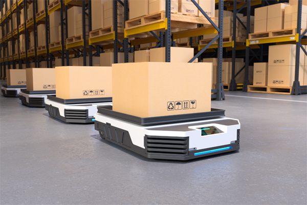
Energy storage systems and uninterruptible power supplies have become integral parts of industrial environments. Vehicles and equipment that require power, such as autonomous mobile robots and AGVs, put the focus on power connectors.
Article Contributed by JAE
High-current connections in industrial equipment traditionally meant bolted busbars or screw-terminal blocks. However, these solutions required assembly time, tool access, and highly skilled field technicians, and ran a risk of loose connections caused by vibration or thermal cycling. As industrial systems have expanded to include small autonomous equipment, new high-current connectors designed for 20A to 500A DC applications have evolved to address serviceability, maintenance, and systems integration. Specifying them correctly requires understanding several design parameters.
Define the current and voltage budget
One starting point is rated current. Connector current ratings specify an ambient temperature with a defined temperature rise. In a densely packed industrial enclosure running at elevated ambient — such as an AGV chassis or a battery rack — the actual operating current should be derated accordingly.
A common rule of thumb is to target 70–80% of rated current at maximum expected ambient. For a 200A-rated connector operating in a 60 °C enclosure, that means planning your conductor sizing and connector selection around 140–160 A of continuous load, not 200 A.
Voltage rating matters independently of current. DC voltage is harder on contacts than AC at the same RMS level because there is no zero-crossing to extinguish arcs during disconnect. In battery and energy storage applications running at 48 V, 96 V, or higher bus voltages, confirm that the connector’s DC voltage rating — not just its AC rating — covers your working voltage with appropriate margin.
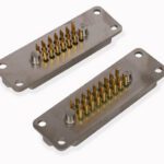
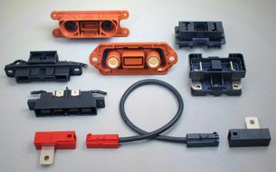
JAE’s cable-to-cable power connectors with series and branch configurations (DW05)
Evaluate the mating environment
In equipment where connectors are mated by docking — battery modules sliding into racks, drawer-style assemblies, board-to-board connections in automated systems — positional tolerance between the mating halves is rarely zero. Mechanical tolerances accumulate across chassis, mounting brackets, and rail systems. A connector with no compliance will either fail to mate reliably or put stress on the PCB, busbar, or cable termination every time it is connected.
Floating connector designs absorb this misalignment mechanically, allowing the connector body to shift relative to its mounting point to find alignment during engagement. The key specification parameters are float range in each axis — typically expressed in millimeters of X, Y, and rotational travel. For board-to-board docking applications, even a modest float range of ±0.8mm can be the difference between reliable automated mating and a connector that stress-fractures its mounting pads over hundreds of cycles. The required float range should be calculated from the worst-case tolerance stackup in the mating axis.
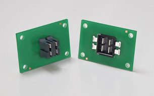
JAE’s floating board-to-board power connectors (DW11)
Safety features
High-current DC connectors in accessible industrial equipment require attention to personnel safety. Finger-safe design, where the connector geometry physically prevents contact with live terminals when the connector is unmated or partially mated, is increasingly a regulatory requirement for industrial equipment.
Beyond personnel protection, short-circuit prevention structures matter in applications using multiple connectors of similar form factor. Installations that use several connectors in close proximity run the risk of mis-mating — connecting the wrong module to the wrong port. Keyed housings and color-coded connectors that physically prevent incorrect connections should be specified.
Sequential mating — where signal contacts engage after power contacts during insertion, and break before them during extraction — is a required feature in any application where live insertion or extraction occurs. This ensures that control signals are not present on a circuit before the power path is established, and that power is removed before the signal path breaks.
Termination method and field serviceability
The choice between screw termination, crimp termination, and busbar-clip termination has downstream implications beyond assembly cost. Screw terminals require tool access clearance and torque verification — both of which are difficult to guarantee in dense assemblies or field service conditions. Crimp termination moves the critical process to a controlled factory environment and produces a connection that doesn’t loosen over thermal cycles. Busbar-clip designs that attach without tools reduce field service time and eliminate torque-sensitive fasteners from the connection entirely. For equipment that will be serviced or reconfigured in the field, the termination method should be evaluated as part of the maintainability requirement.

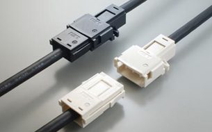
JAE’s busbar docking connectors (DW07)
Specify the Connection Architecture Early
High-current connector families typically offer multiple connection architectures — hybrid connectors that carry both power and signal in a single body, pure power connectors for simple cable-to-cable or busbar connections, and board-mount variants for PCB integration. The architecture decision has significant implications for wiring harness design, assembly sequence, and the total connector count in the system.
A hybrid connector that handles both the 200A power circuit and the 20 signal lines for a battery management system in a single mating operation simplifies assembly, reduces the number of separate connectors that must be aligned and seated, and shrinks the footprint required at the battery interface. The tradeoff is that hybrid connectors are larger and require more careful routing of the combined cable assembly.
Click here to download a visual case study, Connector Solutions for High-current Equipment.
Visit JAE to learn more about connector solutions for Industrial applications.
Like this article? Check out our other Automation and Autonomous Vehicles articles, our Transportation Market Page, and 2025 and 2026 Article Archives.
Subscribe to our weekly e-newsletters, follow us on LinkedIn, Twitter, and Facebook, and check out our eBook archives for more applicable, expert-informed connectivity content.