Measure Twice, Test Once
Measure Twice, Test Once
In the first article in this series on connector testing, I stated that a test is a combination of conditioning/exposures and measurements. All test sequences begin with a measurement to establish the baseline for the parameter of interest, e.g. electrical resistance, prior to a conditioning or an exposure intended to simulate some field condition or degradation mechanism, e.g. durability cycling followed by mechanical shock. Before beginning a discussion of the test groups in the generic test plan described in the first article, it seems reasonable to discuss the measurements that are required in the groups. This article will discuss electrical resistance measurements as used in the first test group.
Electrical resistance is the most common measurement in connector testing. This is reasonable because an increase in connector resistance is a dominant failure mode in connectors. Before discussing electrical resistance measurement procedures, a brief discussion of the basics of connector resistance is in order.
 The figure contains a schematic illustration of a connector contact system with the various resistance components indicated. The overall connector resistance, RO, is the resistance between a contact probe on the conductor as it enters the crimped connection and the appropriate pad on the printed wiring board plated through-hole containing the compliant pin press-in contact. RO is the sum of five individual resistance contributions, RPC, the permanent connection resistances of the crimped and compliant pin terminations, RBULK, the bulk resistance of the receptacle and pin contacts, and RC, the resistance of the separable interface. Although two contacts are indicated at the separable interface, the individual components are difficult to separate and a single value for the contact interface resistance is indicated. In a typical signal connector contact system, the magnitude of these resistances will be of the order of a milliohm for the contact interface resistance, several milliohms for the bulk resistances, and a fraction of a milliohm for the permanent connections. For a typical power contact system, all of these resistances will have a lower magnitude, with the bulk resistances decreasing greater proportionally than the permanent connection and contact resistances. This is due to the fact that power contacts are generally physically larger—reducing permanent connection and bulk resistance—and use higher contact force, therefore, reducing the contact interface resistance.
As noted, electrical resistance measurements measure the overall contact system resistance. The relative stability of these resistance contributions merits attention. The bulk resistances are essentially constant because they depend only on the resistivity of the contact spring material and the geometry of the contact design. The stability of the permanent connections is higher than that of the contact interface resistance because permanent connections are not limited by separability requirements that limit the contact force for both mating durability and mating force reasons. Thus, the contact area in permanent connections is greater than that in separable interfaces because more force and deformation can be allowed. With the increased area comes a larger number of individual contact areas, a-spots, and, thus, a-spot redundancy. Contact area redundancy is always a benefit with respect to resistance stability. Secondly, the residual forces that can be realized in permanent connections are typically more robust than those of separable interfaces. Therefore, in most cases, variations in the overall resistance of a connector, after the conditioning and exposures of a testing program, result from increases in the separable interface component of connector resistance.
There are two basic types of electrical resistance measurements, Low Level Contact Resistance (LLCR, EIA 364D, TP23) and Contact Resistance at Rated Current (CRRC, EIA 364D, TP6). LLCR is generally specified in the testing of signal connectors. In some cases, often a legacy document, CRRC is specified and in some cases, both may be required.
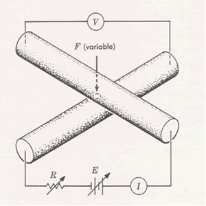
The two measurement procedures differ in their electrical parameters. LLCR measurements are made with an open circuit voltage limited to 20 millivolts. The test current is often 100 mA. The purpose of the low open circuit voltage is to ensure that there is no electrical breakdown of any surface films, oxide films, or contaminants for example, as a result of the measurement. Under these low-level voltage conditions, the measured resistance is that of a metal-to-metal contact interface, which is the design goal for a connector contact interface. CRRC measurements, in contrast, are constant current, the current rating of the contact system without any limitation on voltage. Under these conditions, films and contaminants may be electrically disrupted by the uncontrolled test voltage applied to the sample. Therefore, if the test program requires both electrical measurements, for example in power connector testing, the LLCR measurement must always precede the CRRC measurement. The resistances measured by these two methods will be different. CRRC resistances will be larger than LLCR values. The resistance increase, in the absence of any surface effects, is due to the Joule heating that takes place at the rated current of the connector, as compared to the 100 mA specified for LLCR. Joule heating increases the temperature of the contacts and, therefore, the resistance of the contact spring materials. The difference in resistance observed will depend on the current and the magnitude of the contact spring bulk resistances included in the measurement system. It has been noted that the measured connector resistance includes bulk, contact interface, and termination resistances. For completeness, a resistance measurement technique, a “crossed rod” configuration, that measures only contact interface resistance will be described. The terminology “crossed rod” is clear from the figure. The significance of this configuration is that the only common point for both the voltage and the current paths is the intersection of the two rods. Therefore the measurement includes only the resistance of the contact interface itself. This configuration is generally not possible to realize in measurements on contact pairs. It can be used, however, to eliminate the resistance contributions of lead-in wires in the measurement system.
In the next article in this series, Max Peel, Senior Fellow of Contech Research, will discuss some practical issues in electrical resistance testing.
- Nanocrystalline Silver Alloy Contact Finishes in Electronic Applications - April 6, 2015
- Nanocrystalline Silver Contact Platings - March 16, 2015
- Dr. Bob on Gold Flash Contact Finishes (and Max Peel) - September 22, 2014


