Five High-Frequency Connector Fundamentals
Five AC conditions affect high-frequency connector contact and performance.
By Roland S. Timsit, PhD, PE, Timron Advanced Connector Technologies
Many performance attributes of electrical connectors, such as low contact resistance, maximum current, operating temperature, and others, are often described in relation to DC conditions. Under AC conditions, and particularly at frequencies exceeding hundreds of megahertz, there are characteristics that come into play and affect both electrical contact and overall connector performance. This article will address five of these additional, but fundamental, characteristics.
- Skin Effect
Under AC conditions, current is constrained to flow within a material layer located below the outer conductor surface. The layer thickness, or “skin depth,” decreases with increasing signal frequency (as illustrated for copper in Table 1). The skin effect is a consequence of electromagnetic self-inductance in conductors. At sufficiently high frequencies, the current flow in an electrical contact changes from the pattern illustrated in Figure 1 for the DC case, to the pattern shown in Figure 2, which indicates that, at high frequencies, the current effectively hugs the contacting surfaces. In the latter case, the current flows from the skin layer in one body to the skin layer in the opposite side. Skin conduction and related effects have important implications for connector design and material selection.
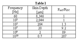
Table 1. The relationship of signal frequency and its effect on the layer thickness and surface heating of copper
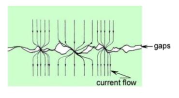
Figure 1. Current flow pattern under DC conditions
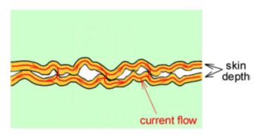
Figure 2. Current flow pattern at high frequencies
- Surface Overheating
Due to the skin effect and the ensuing constraint on the metal volume available for electrical conduction, the resistance of connector pins and receptacles increases rapidly with increasing frequency. The third column of Table 1 illustrates this increase with increasing frequency of the ratio of the AC to DC resistance of a cylindrical copper pin that is 1mm in diameter and 5mm long. In order to minimize Joule heating, the length of pins and receptacles in high-frequency connectors must be kept small, but without compromising the mechanical integrity of the connection with the receptacle. Surface overheating may be exacerbated when coating materials are used. The pins and receptacles of high-frequency connectors are usually plated with materials like gold in order to mitigate oxidation, fretting corrosion, and other contact degradation mechanisms. Consider, for example, the use of 0.75mm of gold on a 1.5-mm nickel underplate on a pin or receptacle. At a frequency of 10GHz, the current flow is restricted to the skin depth of about 1mm in nickel, thus allowing little current spillover into the underlying substrate material. Since nickel is highly resistive, the effective resistance of pins, receptacles, and other connector components may be increased significantly over the DC value, as illustrated in Table 1. This may lead to unexpected overheating if the current amplitude is sufficiently large.
- Surface Roughness Becomes Important
Joule heating also increases with increasing roughness since the length of the current pathway within the skin depth, and hence the electrical resistance of these pathways, is determined by the length of the roughness profile on the surface, as illustrated in Figure 2. Remember, however, that contacting surfaces should not be too smooth to allow for the disposition into micro-valleys of material debris stemming from fretting corrosion and other wear mechanisms. Develop a compromise for an optimum roughness of the contact components of the high-frequency connector.
- Contact Spots Become Less Conductive
Since electrical contact is established at contacting micro-asperities on the mating surfaces, the skin effect restricts the current to flow only along the outer edges of contact spots. This reduces the electrical conductance of the spots from that achieved under DC conditions. Contact resistance thus increases significantly over the DC case under otherwise identical electrical contact geometries. Contact spots will thus overheat at a smaller current amplitude than in the DC case, which often leads to early contact degeneration.
- Capacitive Effects Become Important
It is sometimes argued that electrical interfaces in a high-frequency connection do not require metal-to-metal contact to pass an AC signal since the capacitive reactance across the contact at those frequencies is very small. Capacitive reactance stems from the presence of narrow gaps in the interface (Figure 2), and it may be small enough to short out contact resistance at high frequencies. This view is useful in limited applications, but it is incongruent with requirements for high-fidelity transmission of pulse signals in high-speed communication applications. The absence of metal-to-metal contact precludes passage of the low frequency components of a pulse signal, which can thus lead to severe distortion of the pulse signal shape.
Roland S. Timsit, PhD, PE is President of Timron Advanced Connector Technologies, a subsidiary of Timron Scientific Consulting Inc. of Toronto, Canada. He can be reached at 416-787-8161.

Recently posted:
[related_posts limit=”10″]