Options for Terminating Coaxial Cable
Coaxial/RF cable assemblies comprised $13.5 billion of the $142 billion worldwide market for cable assemblies in 2015. How coax cable and connectors are terminated affects quality and performance, so learn how to choose the right coaxial cable termination options for your application.
Whether it’s ultralight, radiation-resistant sensor cable assemblies in the Mars Rover; a cabled non-magnetic MCX connector in an MRI at 77 Kelvin; or a Low-PIM 7/16 DIN cable in a local cellular base station, performance can be affected by both the quality of equipment and processes used to terminate the connectors and cable.
Termination for Cable Type
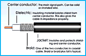
Generic coaxial cable (Source: RF Connectors Division, RF Industries)
Any discussion of termination requires that you first select the cable and connector series. Coaxial cable is any cable with a center conductor surrounded by an insulator (dielectric), which is covered by a conductive shield and, usually, an outer jacket. The shield layer may be solid (rigid or foil) or braided or combinations with one or more layers. The term coaxial comes from the inner conductor and the outer shield having a common central axis. Coaxial cable differs from other shielded cable as the dimensions for all layers/components are carefully controlled to provide constant spacing, so that it can function as a transmission line.
Selection of the proper cable for an application involves several parameters. The characteristic impedance (usually 50 ohms, but it can be 75, 92 – 95, or other values) is determined by the dielectric of the inner insulator and the radii of the inner and outer conductors. A controlled cable characteristic impedance is important as the source and load impedances need to be matched to ensure maximum power/signal transmission and low VSWR. Other important properties that affect selection include attenuation (after temperature correction), velocity of propagation, voltage handling at frequencies involved, and shielding effectiveness.
Coaxial cable may be divided into two types – flexible and rigid. Flexible cables include the basic single-line coax shown above, plus others including biaxial (the old two-line TV cable), twinaxial (twisted pair within a cylindrical shield), triaxial (two coax lines with shields plus a common outer shield), and semi-flexible (also called conformable or hand-formable cable, where the outer shield is braided, filled with solder, and can be hand-shaped for a limited number of bends), and semi-rigid (SR).
Most flexible coax cables use PTFE insulation, solid (for SR) or wrapped in continuous overlapping layers using porous film. In semi-rigid, the outer conductor is extruded metal, usually copper or copper-plated aluminum, which requires precision-length cuts and forming. PTFE is known for its thermal expansion, which can be a problem when connector termination involves soldering. Insulator movement (e.g., expansion) at mating interfaces and at cable-termination areas changes dielectric properties and resultant performance. As a result, SR cables are often thermal-cycled, typically three to five times, before being trimmed to length, so that the expanding Teflon will mechanically adhere to the ID of the outer conductor, which limits further movement. Short end sections of the SR cable are cut off, leaving a stable center section.
Special SR cables that handle extreme temperatures (cryogenic to +2400°F) have very different construction. The insulator is usually silicone dioxide (SiO2), with an outer jacket of stainless steel or titanium, and the cables are hermetically sealed prior to termination. The connector and the cable may be laser-welded together to form a hermetic assembly. Alternatively, the hermetic-end connector may have a pin extension to accept a field-replaceable cable connector.
The other type of cable is rigid-line. These cables comprise two coaxial tubes with supports (usually PTFE) to keep them concentric and use air as the dielectric, usually for short runs in base station high-power RF lines.
Production Rate Determines Termination
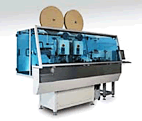
Automated coax cable assembly equipment by Schleuniger Inc.
High production rates and low termination costs are required for commercial high-volume needs, which usually involve frequencies below 6GHz (Bluetooth/WLAN per IEEE 802.11 b/g/n are ≤2.48GHz). This permits use of fully automatic equipment to crimp ultraminiature tape-and-reel data coax connectors such as U.FL and PCIe (MHF4) to miniature cables such as M17/93 (RG 178) or automotive FAKRA connectors to RG-59 cable. For example, Schleuniger’s CoaxCenter 6000 can dual-end cut, terminate, and quality-check more than 1,000 coax cables per hour.
Application quantities usually are inverse to frequency. Precision and performance are foremost for lower-volume microwave and millimeter-wave applications, but there are many different approaches to connector construction and resulting termination methods.
Single Line Methods
Our focus is on single-line assemblies, but the same approaches may apply to each of the contacts in triax and other types. Contacts may be captivated or loose. Some male/plug connectors, whether F-Type or 2.92mm for 40GHz, when terminated with semi-rigid cable, may use the center cable conductor as the connector male/pin contact. This approach is termed “face-and-point,” as the outer conductor is trimmed back to expose the dielectric, which serves as the connector insulator, and the front face is smooth and burr-free. The end of the now-exposed center conductor is finished with a pointed or rounded end. Using appropriate tooling, the cable is inserted into the plug housing where machined stops, secondary crimps (indentations), or other means hold it in place. Pin length and finish tolerances as well as potentials for dielectric movement prompt other approaches where separate contacts are attached to the center conductor.
Contacts may be captivated (i.e., fixed in place) or non-captivated (can move within the insulator). Captivation methods include epoxy and interference-fit plastic beads or discs. Contacts may have tines or barbs attached to hold them in place within insulators, but movement may still occur if the insulator shifts due to mechanical pressure or temperature changes, or insulator material fills in the gaps under the tines. With flex cables, the contact may be attached to the cable center conductor by crimping, soldering, or compression. The cable shield usually is grounded to the connector body by soldering or crimping (with ferrule) or compression nut. The solder-filled outer shield of semi-flexible (formable or conformable) cable is mechanically grounded to the connector housing by crimp-on or screw-on fittings.
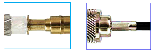
Crimp termination: The illustration at left shows the contact crimped to a cable conductor prior to insertion into the connector. At right is an SMA with the ferrule crimped over the cable shield. (Source: RF Industries, LLC)
Two additional termination approaches deserve review – direct-solder and field-replaceable. Microwave electrical connections require relatively low mating force (when compared to non-RF multi-contact connector types such as D-subminiatures) and as close as possible to full 360-degree cable-to-socket engagement. Direct-solder terminations rely upon this feature by having the OD of the cable conductor fit snuggly into the rear socket of the connector. (The center conductor functions similar to the accessory pin inserting/mating for field-replaceable connectors.) Cables with solid center conductors are preferred, but stranded can be used if tinned and compressed to proper size. The outer shield is soldered to the connector housing to complete the coaxial path.
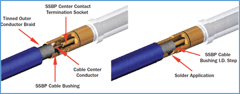
Direct-solder termination: The cable conductor is inserted into the extended connector rear socket, providing a stress-free termination that will accommodate the cable center conductor movement. The view at right is after the cable is inserted and shows where the solder is applied to the cable braid.
Field-replaceable (FR) cable connectors can be in-line cable or flanged for panel mounting. Flange-mount versions may be used to eliminate one of the cables and the associated matings/terminations used with through-bulkhead adapters that require mating cables at both ends. The cable center conductor launches into the rear female socket of the FR connector. As previously mentioned, some SiO2 cables use FR termination to mate with the pin extension of the conductor, but this approach can also be used with unsealed flexible and semi-rigid cables. The standard FR thread-in (sparkplug) connector may be a male plug or female jack based upon application needs.
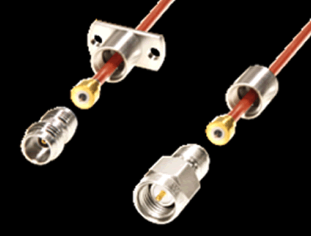
Standard field-replaceable connectors are shown ready to mate with trimmed central conductors extending from bushings attached to semi-rigid cables. The end piece secures the cable bushing and connector together to produce an in-line or flanged panel-mount cabled assembly. Thread-in FR connectors are easily replaced. The FR cable-to-socket mating interface permits stress-free cable movement. Electrical performance sees benefits by eliminating soldering of the center conductor. (Direct-solder and field-replaceable cable graphics by Southwest Microwave)
Problems with Bad Termination
While opens and shorts are readily detectable, improper termination of coaxial cable may cause problems not readily traceable to the cable assembly. Poor crimping (wrong tool or turret setting, etc.) or poor soldering results in uneven impedance matching for more return loss (higher VSWR). Less than complete 360-degree grounding reduces shielding effectiveness.
During handling, the spacing between the shield and the center core must be kept consistent. The results of careful work and testing can be negated by improper packaging that can kink, crush, or sharply bend a coaxial cable, which may degrade the signal more than poor termination. If this happens, the unfortunate user must resolve the differences between test data and unexpected performance “as received.” Stripping away the dielectric insulator and terminating the core and shield manually, as you would with ordinary wire, also leads to signal loss and increases the potentials for RF interference. At microwave frequencies, cable trim that causes any nicks to the center conductor or angled dielectric cuts can affect results.
Low-PIM cables are especially susceptible to termination problems. Contamination from cracked or cold solder joints and corrosion can create nonlinear junctions. Cutting the cable can create metal debris and if these particles remain in the cable or get into the finished connector, they can cause PIM if they come in contact with a current-carrying surface. Contaminants can be a source of intermittent PIM if the cable assembly is flexing and would be difficult to locate and remove. Careful termination improves production yields and microwave performance.
[related_posts limit=”15″]
- New Circular Connectors Add to Multi-Billion Dollar Market - January 9, 2024
- Counterfeit Components Ground Airlines - December 12, 2023
- Cables, Connectors, Waveguides, and Hybrid Products for up to THz at IMS 2023 - July 11, 2023


