Navigating the Connectivity Challenges of Mobile Electrification
Understanding the connectivity issues common to electric vehicles and aircraft can help designers handle the multiplying number of electrification projects.
The trajectory of innovation in electric vehicles (EVs), electric vertical takeoff and landing (eVTOL) aircraft, and aerospace applications seems to be going everywhere all at once. The expanding number of electrification projects makes it challenging for system designers and electrical wiring interconnect system (EWIS) engineers to identify the optimum interconnects.
While each ground, air, and space application faces its own specialized needs, understanding common issues gives designers greater confidence when navigating today’s rapidly evolving connectivity ecosystem.
Transferring connectivity know-how from cars to aircraft
EVs may not seem to have much in common with electric vertical takeoff and landing (eVTOL) aircraft or its short-runway takeoff (eSTOL) and conventional takeoff (eCTOL) cousins. Nevertheless, many architectures used in designing and manufacturing electric cars cross over to electric aircraft. For example, EVs began with 400-volt battery packs, but many now employ 800 volts exactly where aerospace and electric-aircraft applications typically operate. That commonality has encouraged the development of architectures and compatible connectors that can handle the battery pack, the power distribution unit, and inverters and motors. Although more power is needed due to more motors in eVTOLs than EVs, the transfer of know-how between technologies is a tremendous advantage for system designers looking for an integrated solution.
System architecture: Adopting a system-architecture approach using compatible cabling, connectors, and power-switching components simplifies the task of engineering an integrated solution. A qualified manufacturer who can provide a map of products that fit your project from the get-go is a valuable asset. Optimizing interconnectivity across various subsystems (e.g., power management, avionics, databus, etc.) at every interconnect along the wire improves size, weight and power (SWaP) factors, simplifies the production process, and speeds time to market.
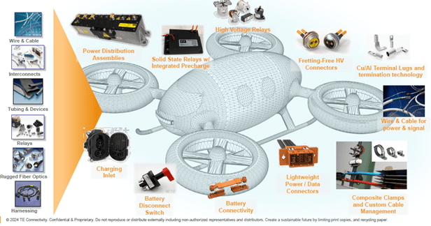
Ecosystem of connectivity products in a generic eVTOL project. Courtesy TE Connectivity.
Standards and certification: It is also vital to partner with a qualified manufacturer to gain insight into the standards and certifications that may apply to your project. SAE, FAA, and MIL standards, as well as the Technology Readiness Level (TRL) may apply to the selected part whether it’s used in charging, propulsion, ground support, cockpit display, avionics, and other systems.
[SAE International provides standards for electric vehicles and numerous E-40 Electrified Propulsion standards that cover eVTOL aircraft. Diagram courtesy TE Connectivity.]
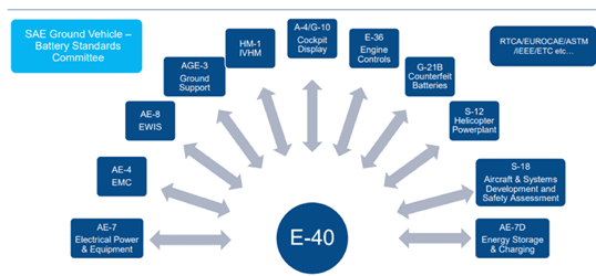
SAE International not only provides standards for electric vehicles. Numerous E-40 Electrified Propulsion standards cover eVTOL aircraft. Diagram courtesy TE Connectivity.
With aircraft, the FAA certification process is also critical. Three primary certificates verify that all regulatory requirements for the aircraft design, manufacturing process, and commercial operation have been met. These certificates encompass rigorous testing and evaluation by the relevant authorities. Each phase must be met without any change to the aircraft, otherwise recertification is required.
That’s why, at the beginning of the design process, it’s helpful to know that the interconnect manufacturer can provide metrics and custom test setups to verify product performance in various conditions, including temperature cycling, fretting corrosion, voltage, vibration, flexion, etc.

eVTOL tilt rotors bend cables thousands of times during a single flight. A special testbed can measure a cable’s flexibility, resilience, and performance. Courtesy TE Connectivity.
More high-voltage, high-power challenges
While there are some commonalities in battery-pack and charging voltages between EVs and smaller eVTOLs, the requirements of propulsion and navigation in larger electric aircraft and aerospace projects are more demanding.
Lightning: A dramatic example is a direct lightning strike, which can expose the craft to a 100,000 to 200,000 ampere current. Per FAA guidelines, high-quality electrical bonding, wire bundle shielding, and wire bundle routing, as well as a low-impedance, high surface area path to ground for all systems are required to handle the charge.
High operational voltages: In operation, high network operating voltages (potentially as high as >3kV DC) impose extreme electrical stress on relays and contactors used for propulsion motor power switching, battery charging management, air conditioning for passengers, and other auxiliary functions. High voltage relays and contactors are available that can meet peak load capacity demands as well as operating temperature, coil efficiency, short-circuit protection, breaking capacity, and other critical requirements.
Higher voltages and power exacerbate other problems. Dust, moisture, exhaust, and other pollutants can create pathways for current to travel across a material. Electric discharges can then occur, risking an explosion–whether in flight or on the ground when fast charging is performed in high-moisture environments. An arc-tracking index can evaluate how readily a given voltage travels across a material’s surface if it’s clean or polluted. Wire can be selected with dual-wall construction using radiation cross-linked modified materials that resist carbon arc tracking even when contaminated with hydraulic and de-icing fluids.
Corona discharge: The effects of voltage differences become more extreme as altitude, temperature, and frequency increase. A given material may support a partial discharge inception voltage (PDIV) or a partial discharge extinction voltage (PDEV) resulting in a potentially destructive corona discharge. A Paschen-curve map can help evaluate how the thickness of dielectric insulation performs at specific altitudes and distances between conductive surfaces.
Moisture and air pressure: Higher altitudes also promote water seepage into gaps in components and eventual corrosion. Using appropriate dielectric materials and design constructions that control air gaps will minimize the effects of changing air pressure.
Superconductors: Extremely efficient electric propulsion systems using liquid hydrogen are being developed. Liquid hydrogen (-253 °C/-423 °F) enables cooled materials to function as superconductors in the electric-motor system driving the propellors. Of course, a cryogenic environment is extremely demanding for a whole array of connecting technologies—power distribution, relays, connectors, cable harnesses, battery interconnects, and charging systems—which must be specially designed for these temperatures.
Battery charging: In battery charge cycles, a balance must be struck between higher energy transfer and higher temperatures. During high-power charging (HPC), individual components are subjected to temperature extremes at resistance points along the high-voltage path. Every microohm (υΩ) of resistance must be minimized. Areas to reduce resistance include cable terminations, contact interfaces (crimps and contact types), and contact materials. Liquid-cooled cables and laying cables in convective- or conductive-cooling heat sinks are also solutions. Thermal sensing and thermal modeling can be employed to design a cooling “ecosystem” for charging systems on the ground—and to detect high temperatures during power surges on landing and takeoff.
Thermal cycling: Exposure to high peak and low cryogenic temperatures stresses metal, glass, and polymer materials. Minor imperfections are aggravated, compromising strength and degrading performance. Higher temperatures also increase vapor pressure and the rate of chemical reaction and outgassing. Materials must be selected for every component — from sensors to wire and cable to connectors and relays — to handle peak temperatures and thermal cycling stress.
Near absolute zero: Know-how about temperature cycling extends far beyond eVTOLs for qualified manufacturers experienced at handling 2.725 Kelvin (-270.4 °C/-454.72 °F) temperatures for LEO-satellite interconnects operating in the vacuum of space. Interconnects on onboard LEO-satellite systems operate within a -65 °C to 125 °C range depending on orbit height, solar heat gain moderated by satellite spin, and heat generated by electronics. Interconnects for propulsion system components, external latches, sensors, and solar panels are subject to more extreme temperatures.
Outgassing: Outgassing occurs when gases trapped in nonmetallic materials — such as polymers used in connector inserts, seals, adhesives, or potting materials — are released in the vacuum of space or by high temperatures. Besides contributing to corona discharge as previously discussed, released gases can condense on and contaminate sensitive surfaces, eventually degrading the performance of charge-coupled device (CCD) sensors in satellites, thermal radiators, or solar cells.
NASA ASTM E595-77/84/90 testing and the MIL-W-22759 (M22759) | SAE AS22759 specifications cover a material’s performance when exposed to high heat or the cold vacuum of space. Anything considered a low-outgassing material must meet requirements for a total mass loss of 1.00% or less and a collected volatile condensable material (CVCM) of 0.10% or less.
Inorganic materials are immune from outgassing and can be used, for example, in connector shells employing aluminum with an electroless nickel finish. Materials can also be selected that meet NASA requirements for low outgassing in thermal oven bakeout testing.
Get the services of a capable partner to meet tough challenges
Standardized testing. By measuring interconnect performance, standardized testing can help answer such questions as: How does the interconnect handle temperature ranges in hot or cold environments? How does it handle the typical chemicals a vehicle will be exposed to on the ground or in the air? What about de-icing? What about electromagnetic radiation? What about resistance to oxidation?
Maintenance and service. Maintenance procedures must also be considered. How is charging performed? Are batteries taken in and out? What is the power cable hookup? Regarding the infrastructure for quick charging, where are charge access points located? Who has access to them? Do connectors and wiring harnesses accommodate inspection and replacement?
Finding a partner. Today, the frontier of electrification is rapidly expanding thanks to enterprising innovators and strategic government-backed programs. It pays to partner with a connectivity leader with qualified SpaceVPX, VITA, NASA, ESA, and MIL-SPEC compliant products—but also with COTS and COTS+ components—to support projects on strict time and cost budgets. Designers who can access a comprehensive array of products find it easier to engineer an integrated solution.
Moreover, getting bespoke product design capabilities, tooling, supply chain management, cost control, and certification support all from the manufacturer instills the confidence that your project will reach its goals on the ground, in the air, or even up in orbit.
Visit TE Connectivity to learn more about innovative connectivity solutions for eVOTL and UAM applications.
Like this article? Check out our other EVs and HEVs and Innovation articles, our Military and Aerospace Market Page and our 2025 Article Archives.
Subscribe to our weekly e-newsletters, follow us on LinkedIn, Twitter, and Facebook, and check out our eBook archives for more applicable, expert-informed connectivity content.
- Navigating the Connectivity Challenges of Mobile Electrification - July 15, 2025