Surviving the Challenges of Environmental Monitoring: Rugged Connectors for Sensor Technology
Sensors are on the front line of an application’s exposure to harsh operating conditions. Specifying the right connector for sensors ensures reliability and performance for the entire sensing system, even under duress.
Detection of environmental conditions requires connectors for sensors that can survive the harshest situations. Temperature fluctuations, airflow and air pressure, high vibration, corrosive gases, and humidity are just a few of the factors that pose challenges for electronics that must maintain a secure electrical connection in order to maintain stable operation. Several aspects of connector design can help the sensors and the entire interconnect system thrive in a rugged environment.
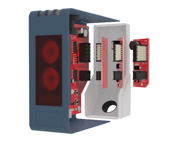
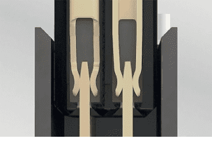
An example of connectors within a modular sensor.
Vibration
Often considered to be the most common environment challenge, vibration can impair the connections between connectors as well as the connectors’ contact to the PCB. The design of a connector can prevent signal interruptions due to vibration in several ways. One way is to opt for a “board-lock,” or a metal clip located at the sides of a connector that can be soldered onto the PCB, anchoring the connector firmly to the board. Board-locks prevent a connector’s contacts from dislodging during operation and they can absorb the mechanical stress caused by vibrations.
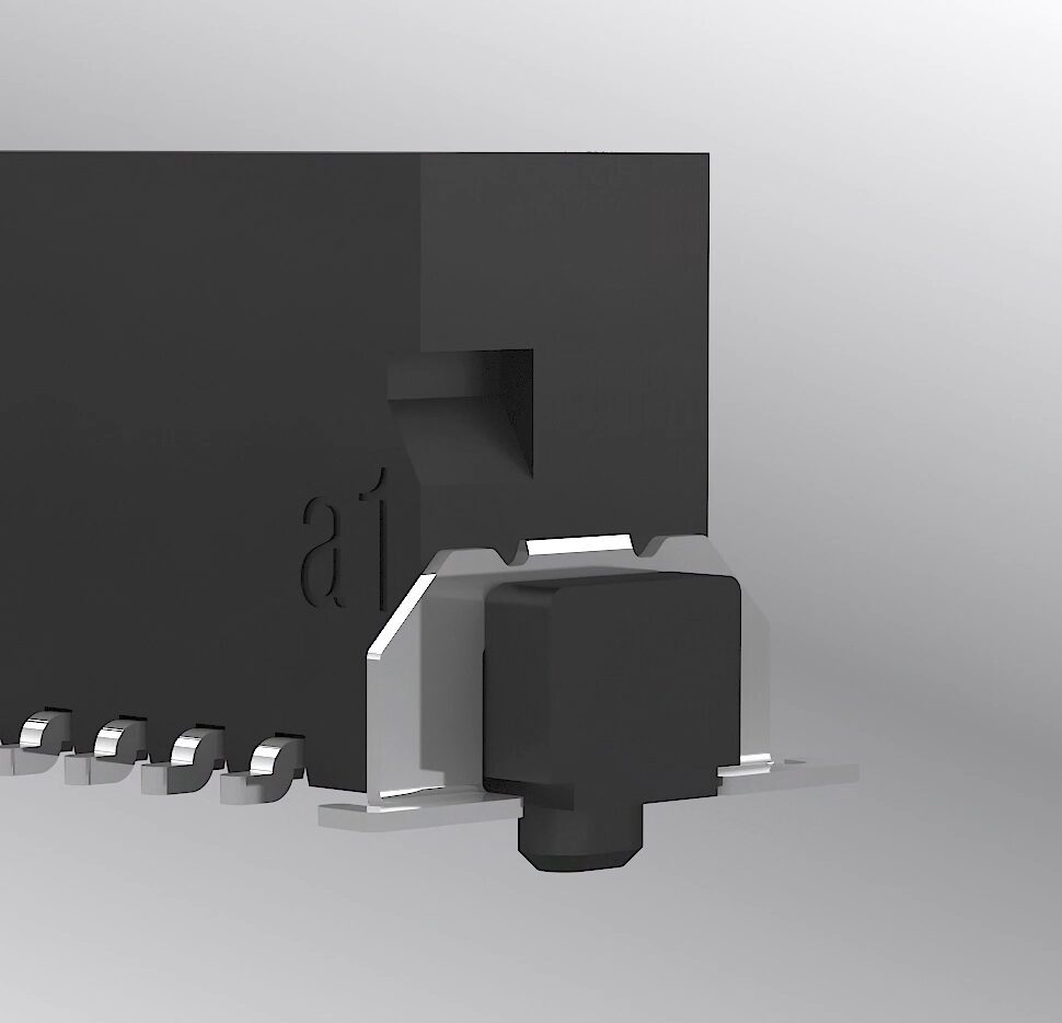
An example of a connector with both a board-lock and a positioning pin for precise positing during processing, as well as a reliable PCB connection from ept’s One27 1.27 mm PCB connector family.
Another way a soldered connector can cling to a board despite vibrations is by having specially designed contact feet that allow a solder meniscus to form during the soldering process, creating an optimum connection to the PCB’s soldering pads. Also, the added option of positioning pins on the underside of a connector can ensure that the connector has been placed precisely on the board during mating, before soldering even begins. This can prevent the possibility of an incorrectly placed connector, ensuring later performance is not disrupted by errors made during mating to the PCB.
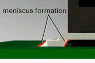
A meniscus formation zone as illustrated using an ept One27 1.27 mm PCB connector. The formation of a meniscus on a solder is a sign of a rugged, stable, surface mount connection.
Protecting contacts within a housing can greatly reduce risks from high vibration. By submerging contacts within an encompassing insulating body, damage to them becomes virtually impossible while also preventing contact deformations during installation and operation. Improper contacting during mating is one of the largest causes of later operational failure.
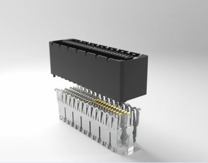
Example of a connector with a housing (at top, in black) that thoroughly encases the internal double-sided contacts (illustrated below the housing). In this example, the Zero8 0.8mm PCB connector protects the contacts from damage and forms a barrier against vibration.
Choosing specialized contacts: Protection against multiple environmental threats in connectors for sensors
Most conventional SMD connectors establish contact via a common “male and female” pin-and-hole connection concept. The problem with this classic connection concept is that the contact point can become disconnected in a rugged environment due to a variety of causes. Mechanical load, vibration, and electric shock are frequent causes of connection failure with this type of contact. An improved solution is needed for the success of an environmental sensor design. Several different types of specialty contact designs have been created to address these difficulties. Two examples are connections made with dual-beam contacts and connections made with “genderless” blade-and-spring contacts.
A dual-beam contact offers greater contact security in environments with high vibration. The design involves the use of a double-sided female contact, which ensures at least one of the two female contacts is constantly touching the male contact, even if the two connectors are pushed against one another or during vibrational shifts between the PCBs.
Dual Beam contacts offer additional stability to ensure contact is constant during high vibration. This example is of an ept One27 1.27 mm PCB connector. The vibration properties of the One27 connector have been certified for a frequency range of 10–2000 Hz in accordance with the IEC 60068-2-6:2007 standard. The shock properties have been confirmed at an acceleration of 50 G in accordance with IEC 60068-2-27:2008.
A connection where the plug and socket each have a blade contact and a spring contact creates a “genderless” connection. This connection therefore establishes high redundancy and thus maximum contact reliability, as double contacting is made on each pin. As a result, a gender-neutral contact system ensures safe, robust, and gas-tight contacting despite external influences such as shocks, vibrations, thermal cycles, and even corrosive gas.
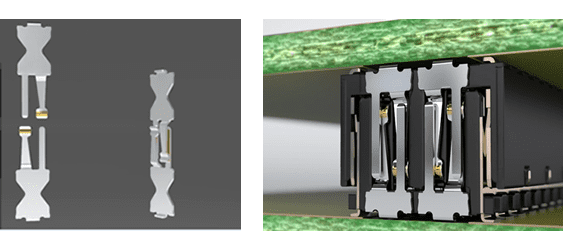
Example of “genderless” blade-and-spring contacts on an ept Zero8 0.8mm PCB connector. Both plug and socket have a blade and a spring contact (left), creating a robust and genderless connection safe from vibration, thermal cycles, and corrosive gases that could otherwise prove detrimental to the signal.
Scalability challenges
Circuit boards must be able to connect to one another to communicate signal and current, but the choice of connector dictates the possibilities for PCB combinations. A connector choice should expand design options, rather than limit them. One of the most crucial aspects of choosing a connector in the design phase is to determine its scalability within the project. Some manufacturers are slowly expanding their options to also include low-profile and high-profile connector variations, allowing for customizable stack height distances between boards. The addition of cabling also can offer seemingly infinite distance expansion possibilities for modules. The problem of connecting a horizontal board with a vertical one in a sensor system can also be addressed by using a right-angled connector. Scalable pin and row counts – as well as the pattern in which the pins are placed within the housing’s rows – can also determine current capability, overall contact resistance, as well as a connector’s tolerances for voltage.
ept’s Zero8 connectors can be used to accommodate unique board spacing ranging from 6.00 mm up to 21.00 mm, as well as right-angled connections.
High tolerance compensation during mating as well as in mated state
Connectors need to be as rugged as possible during all phases of use, including processing and handling as well as during operation. Generally, for tolerances and misalignment compensations, the industry standard is + or – 0.5 mm and about 2°. Using a connector that exceeds these standards for a rugged sensor allows for far greater flexibility in design, while also preventing loss of signal or damage during mating and operation. The mating and intermating of scalable connectors with high tolerances is perfect for use in a modular sensor design, while also permitting the most productive possible use of available real estate on the surface of a PCB.
While mated, the Zero8 connector family also has an impressive tolerance compensation of 0.4 mm in the horizontal and diagonal directions, and up to 2.3 mm in the vertical direction. ept has verified 500 mating cycles with 12 connectors on one printed circuit board according to DIN EN 60512-9-1:2010-12 in an accredited laboratory.
External sources of interference
Environmental sensors systems can come in both wired and wireless options. Wireless sensors are appealing due to their simplified installation – without the need for expensive installation of wiring systems – but wireless sensors can also be more vulnerable to electronic interference from outside sources, especially in cases where many other electronic signals are in operation in close proximity.
Hacking is another electrical interference source that is a massive external threat to both types of sensor systems. Attempts by outside individuals to intentionally interfere with electronic systems is a huge concern for many industries.
In the case of a connector, the physical hardware itself can help protect a sensor’s internal signals from both unintended disruptions from nearby electronics and adjacent components, as well as external hacking attempts. A connector that has a built-in physical shield can help create and maintain an unimpeded signal during operation. A metal shield reliably diverts interference currents via the multiple contacting points to both PCBs in the direction of the ground connection. In simple terms, a shield “keeps in” the connector’s signal while also “keeping out” any signals that could disturb the connector’s operation. A shield can prevent a connector from causing unintended EMC interferences as well as being affected by outside EMC interferences, protecting the overall integrity of the signal.
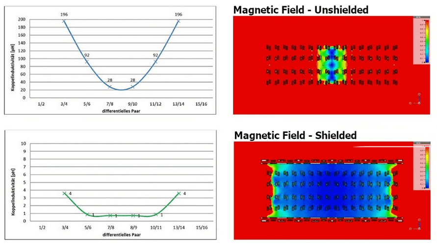
Simulation of the operation of an unshielded (top) connector and a shielded (bottom) connector.
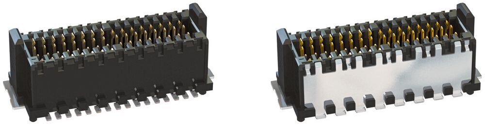
A connector without a shield (left) and one that has the added option of a metal shield (right) to protect signal integrity while resisting outside sources of EMC interference.
The abilities and specialty design of a board-to-board connector can either limit or expand a PCB designer’s opportunities within a sensor project. Designs must anticipate the challenges that the hardware will face in the field. Luckily, many connector components tailored for rugged environments can achieve optimum monitoring capabilities within an environmental sensor system.
Explore connector solutions for sensor systems and other harsh environments at ept USA.
By Anne Louden and Josh Jacobi, ept, USA Marketing Team
Like this article? Check out our other Connectors, and Contacts articles, our Sensors & Antennas Market Page, and our 2023 Article Archive.
Subscribe to our weekly e-newsletters, follow us on LinkedIn, Twitter, and Facebook, and check out our eBook archives for more applicable, expert-informed connectivity content.