What is a MIL-DTL-28748 Connector?
MIL-DTL-28748 (formerly MIL-C-28748) is a U.S. military specification that defines rectangular, rack-and-panel electrical connectors with non-removable solder-type contacts or removable crimp-type contacts. It is commonly specified for airborne, ground-support, and shipboard equipment as a compact, high-contact-density, multi-source connector interface that is already proven for severe-environment military and aerospace use.
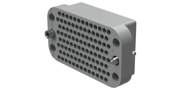
Positronic’s GMCT conforms to MIL-DTL-28748. Amphenol Positronic MIL-spec connectors are also stocked by Mouser.
Technical Standard
MIL-DTL-28748 was first issued as MIL-C-28748 in 1970 by the U.S. Department of Defense. DLA Land and Maritime (formerly Defense Supply Center Columbus) is the current preparing activity and maintains the Qualified Products List, QPL-28748. The base document has since been revised through Amendments A (1985), B (1991), C (1998), and the current active issue, MIL-DTL-28748E (2021); each revision has preserved mechanical and electrical interchangeability with earlier versions of the connector.
Design Highlights
The shell, insert, hardware, and contact interfaces are fully defined by the government spec, so a design isn’t locked to one vendor. The connector contains many contacts in a small rectangular footprint (from about 4 up to over 100 positions), uses captive dual jackscrew hardware for a positive, vibration-resistant lock, and includes polarizing guide pins so a plug can’t be mis-mated with the wrong receptacle. Because qualification testing already covers shock, vibration, temperature cycling, and humidity, designers get proven reliability without running their own environmental test program, and suppliers continue to add finer-pitch, higher-density insert arrangements for newer, more space-constrained avionics and instrumentation packages.
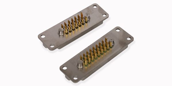
Hermetic Seal Series 5000 connectors are engineered to meet the specifications of MIL-DTL-28748.
Markets & Applications
MIL-DTL-28748 connectors are used across aerospace and avionics, military ground and shipboard electronics, spaceflight hardware, Test & Measurement applications, and portable military equipment.
Typical uses include avionics racks and LRU interconnects, telemetry and data-acquisition packages, ground support test equipment, and shipboard electronic enclosures. Several insert and hardware configurations are also qualified to NASA Goddard Space Flight Center specifications (GSFC S-311-P4 and S-311-P10).
Reading the Part Number
A military PIN such as M28748/7-B00E1A breaks down as follows: the base number identifies MIL-DTL-28748; the slash number (/7) points to the specification sheet that defines the connector’s envelope and contact type; the letter (B) sets the insert size and contact count; and the trailing code (00E1A) calls out the hardware — jackscrew style (fixed or turnable), length, and finish. Commercial part numbers, such as Positronic’s SGMC9S0ESS0000, follow similar logic but use the supplier’s own series, contact-count, and option codes instead of the military designator.
Technical Specifications
Values below are from the MIL-DTL-28748 base specification; for exact ratings for a given connector consult the manufacturer’s data sheet.
| IDENTIFICATION | |
| Governing Standard(s) | MIL-DTL-28748 (formerly MIL-C-28748) |
| Standard Issuing Body | U.S. DoD / DLA Land and Maritime (formerly Defense Supply Center Columbus) |
| Common Name / Series | M28748; commercial lines include Positronic SGM/SGMC/GM/GMCT and Vishay Dale MM/MMS/MMP/CMMS |
| Industry Category | Rectangular, Rack-and-Panel (MIL-Spec) |
| MECHANICAL SPECIFICATIONS | |
| Shell / Housing Shape | Rectangular, rack-and-panel plug and receptacle |
| Shell Material & Finish | Insulator body of glass-filled diallyl phthalate or PPS thermoplastic; aluminum alloy (anodized) or corrosion-resistant steel (passivated) hardware; noncorrosion-resisting parts cadmium- or zinc-plated |
| Size / Shell Size Codes | Insert-size letter designators per specification sheet, spanning roughly 4 to 100+ contacts across standard- and high-density lines |
| Mounting Type(s) | Panel/chassis mount (fixed jackscrews); cable mount (turnable jackscrews) |
| Plug / Receptacle Styles | Straight plug and receptacle; cable-mount plug with fixed or turnable screwlock hardware |
| Mating Cycles (rated) | 500 cycles of insertion/withdrawal (durability test per MIL-STD-1344) |
| Locking Mechanism | Dual captive jackscrews (fixed or turnable), per MS18194–MS18197 |
| Keying / Polarization | Polarizing guide pins/sockets located adjacent to the No. 1/A contact prevent incorrect mating |
| CONTACT SPECIFICATIONS | |
| Contact Arrangements | Defined per specification sheet; roughly 4 to over 100 contacts depending on insert size and density |
| Contact Size(s) / AWG | Sizes 16, 20, and 22 (per specification sheet), accommodating 16–26 AWG wire |
| Contact Material & Plating | Copper alloy (typically phosphor bronze) contacts; gold plating per ASTM B488 over a nickel underplate |
| Termination Method(s) | Nonremovable solder-cup contacts and removable crimp contacts (MIL-C-39029 family); PCB solder-tail and press-fit options offered by some suppliers |
| Current Rating (per contact) | 5.0 A (size 22) to 13 A (size 16) on solder contacts; crimp contacts rated similarly by wire size (see Table I of the base spec) |
| Voltage Rating | Dielectric withstanding voltage of 1,000–2,000 VAC (60 Hz rms, sea level), depending on contact size and termination type |
| Insulation Resistance | 5,000 MΩ minimum, initial (per MIL-STD-1344 Method 3003) |
| Contact Resistance | 50–70 mΩ maximum, depending on contact size and test condition |
| SEALING & ENVIRONMENTAL | |
| IP / Sealing Rating | Not sealed — no IP rating is defined; the interface is not intended for immersion |
| Sealing Type & Material | None (unsealed rack-and-panel interface) |
| Operating Temperature Range | –55 °C to +125 °C |
| EMI / RFI Shielding | Unshielded in the base configuration; shielded shells are available on select specification sheets |
| Vibration & Shock (rated) | Per MIL-STD-1344 Method 2005 (vibration) and Method 2004 (shock), test condition per specification sheet |
| MATERIALS & COMPLIANCE | |
| Insulator Material | Diallyl phthalate (ASTM D5948) or PPS thermoplastic (ASTM PS2) |
| RoHS / REACH | Base MIL-spec hardware historically uses leaded finishes/cadmium plating and is not inherently RoHS compliant; RoHS-compliant, lead-free options are offered by some qualified suppliers — verify by part number |
| Qualification / QPL | QPL-28748, administered by DLA Land and Maritime |
| Applicable Test Standards | MIL-STD-1344 (connector test methods); MIL-STD-202 (component test methods) |
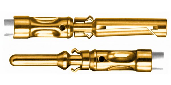
Winchester Interconnect’s 100 Series Contacts offer a flexible and reliable solution for rack and panel equipment. Commonly used with Winchester’s MRAC series and the DLA qualified MIL-DTL-28748 rectangular connectors
Suppliers
Manufacturers: AMETEK, Hermetic Seal, Positronic, Winchester Interconnect, Vishay
Distributors:
Qualified and commercial-equivalent parts are available through franchised distributors including CDM, DigiKey, Mouser, and TTI Inc.
Related Products
MIL-DTL-38999 (D-Sub)
MIL-DTL-83513 (Micro-D)
Like this article? Check out our other Meet the Connector and Connector Basics articles, our Military and Aerospace Market Page, and our 2026 Article Archives.
Subscribe to our weekly e-newsletters, follow us on LinkedIn, Twitter, and Facebook, and check out our eBook archives for more applicable, expert-informed connectivity content.

- Connecting the Next Generation of EV Batteries - October 6, 2026
- What is an Antenna Connector? - September 29, 2026
- USB-C Serves Industrial Design with Rugged Variants - September 22, 2026