What are SMA Connectors?
Meet the Connector: SMA coaxial RF connectors
SMA (Sub-Miniature version A) coaxial RF connectors are single-line, threaded coupling connectors, available worldwide in many versions including termination options, different levels of environmental sealing, and electrical performance.
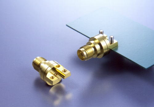
JAE end-launch type SMA connector
The connector has a characteristic 50 Ω impedance and was originally designed for use from DC (0 Hz) to 12 GHz. This has, however, been extended over time and variants designed to work at 18 GHz and 26.5 GHz are now available.
SMAs were originally designed at Bendix Research (now part of Amphenol) in 1958 as the BRM connector, an acronym for Bendix Research Miniature connector. In 1962, the BRM’s designers left Bendix and formed Omni Spectra Inc., where they created the OSM (for Omni Spectra Miniature) for 26.5 GHz. The OSM (future SMA) established the foundation for the miniature microwave connectors that are used today. The same engineers founded Southwest Microwave (SMI) in 1981, where they developed an exceptional thick-walled SMA with uniquely stabilized Teflon that limited expansion at 165˚C to only about 0.001 inch at the interface. This SMA earned the title of SuperSMA; it was one of the first field-replaceable types and prompted industry usage of field-replaceable connectors for better performance and reliability, especially for hi-rel, medical, and aerospace applications.

Cinch Connectivity’s SMA vertical launch coax connectors
MIL-Spec Standards
MIL-spec documentation first occurred in 1965. Omni Spectra had copyrighted the term OSM, therefore DSCC named it SMA (for Subminiature Type A). Later, a smaller-than-OSM/SMA series was developed, termed OSSM and standardized as SSMA. SMAs are standardized per MIL-PRF-39012 and CECC 22110/111, but most production is outside of spec-coverage (e.g., 39012 does not include field replaceable versions), or for commercial applications such as telecom or test equipment that do not need spec-approval.
Even today, most RF connector manufacturers (especially offshore) do not have the internal transmission line design knowledge or the specialized higher tolerance manufacturing capabilities needed to produce SMAs for low VSWR at higher frequencies. From the start, many companies made look-alike copies of the SMA using MIL-spec drawings that defined the mating interface but did not detail the internal construction that controls performance. Many were barely useful to 3 or 5 GHz with degraded performance at higher temperatures (due to Teflon expansion at the interface which changed the air gap dimensions), which is still true for many of today’s SMAs that nevertheless are acceptable for many current lower frequency applications.
Polarity
A standard-polarity SMA male connector has a 0.9 mm diameter center pin surrounded by a barrel with inside threads, and the standard SMA female connector has a center sleeve surrounded by a barrel with outside threads. The gender assignment corresponds to the innermost electrical component. The center pin is the same diameter as the center of RG402 Coax so that connections can be made without discontinuity. The pin is formed from the coax itself.
A reverse polarity RP-SMA, available in all styles, reverses the gender of the interface to allow for port identification and prevent the mating of incorrect antennas or devices to equipment. The pin and sleeve are swapped so that the male RP-SMA has a center sleeve surrounded by an inside-threaded barrel, and the female RP-SMA has a center pin and an outside-threaded barrel.
SMA materials
Environmental demands dictate material selections for the manufacture of the connectors and surface plating. Use in harsh environments calls for IP68 versions of both popular standard SMA connectors and customer-specific bespoke designs.
SMA connectors usually have a brass or stainless-steel body. The finish is typically nickel or gold on SMA connectors, while the stainless-steel body has a passivated or gold finish. The center contact/pin of a SMA connector is usually made of brass or copper with a gold finish.
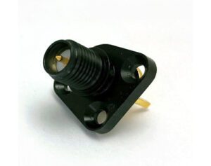
COAX Connectors’ SMA Reverse Polarity, Straight 3-Hole Flange-Mount PCB Jack is IP68-sealed un-mated with a black non-reflective nickel finish, gold-plated contact, and PCB solder body.
How to Specify
For proper product selection, consider maximum operating frequency and operational parameters such as levels of vibration, shock, minimum and maximum temperatures, and any additional needs, such as special testing for hi-rel or space/SATCOM applications. At microwave frequencies, mechanical differences affect electrical performance. Pretty gold-over-nickel plated SMAs belie the fact that the housing is made of relatively soft brass and the nickel underplate is needed to help prevent corrosion from showing up. Higher performance SMAs often use more expensive stainless steel housings, but the application may not need this.
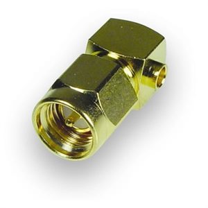
There are SMAs with push-on mating, 90˚ bends, glass-to-metal hermetic sealing, Low PIM, and non-magnetic construction, panel and board-mount, plus adapters to enable connecting SMAs to other series of coax connectors. Some SMAs let contacts float within the Teflon insulators while some have barbs on the contacts to help hold them in position; some designs use epoxy to hold components together (indicated by the two “black epoxy-filled holes” seen in housings, which unfortunately serve as windows for RFI radiation). Higher performance SMAs usually use internal interference-fit discs to secure components in position. A slightly smaller version, termed SMC, is available. Some suppliers offer a bayonet coupling version, called SMB, for 6 GHz. The SMB interface was adopted for automotive connectors called FAKRA.
Design Notes
Mounting Configurations The key mounting configurations include panel mount (2-hole and 4-hole flange), PCB mount, edge mount, bulkhead mount, SM, and through-hole mount.
Characteristics 50 Ω impedance for use from DC (0 Hz) to 12 GHz, with variants available to work at 18 GHz and 26.5 GHz.
Materials The SMA connector body is typically either brass with a nickel or gold finish or stainless steel with a passivated or gold finish. The connector center contact/pin is most often brass or copper with a gold finish.
Markets, Sectors, Applications SMA connectors are used in telecom, medical, industrial, factory automation, and robotics markets. Applications include microwave systems, hand-held radio and mobile telephone antennas, Wi-Fi antenna systems and USB software-defined radio dongles, and radio astronomy, particularly at higher frequencies (5 GHz+).
Suppliers SMA connectors are available from a number of connector suppliers, including Amphenol RF, Bulgin, Cinch Connectivity, COAX Connectors, Hirose Electric, I-PEX, ITT Cannon, JAE, JPC Connectivity, SV Microwave, TE Connectivity, and Trexon.
Related products
- RF connector
- SMB connector
- SMC connector
- BNC connector
- TNC connector
- N connector
- Coaxial cable
- Optical fiber connector
- MMCX connector
- MCX connector
Learn more about RF coaxial connectors.
Visit the Preferred Supplier pages of the companies included in this article: Bulgin, Cinch Connectivity Solutions, COAX Connectors Ltd, Hirose Electric, I-PEX, ITT Cannon, JAE, JPC Connectivity, SV Microwave, TE Connectivity, and Trexon.
Like this article? Check out our other Meet the Connector, Wire & Cable and New Technology articles, our Datacom/Telecom Industry articles, and 2022 Article Archives.
Subscribe to our weekly e-newsletters, follow us on LinkedIn, Twitter, and Facebook, and check out our eBook archives for more applicable, expert-informed connectivity content.
- Mezzanine Connectors Product Roundup - April 16, 2024
- Out Now! New eBook Shares Bright Ideas for Electrification - April 16, 2024
- What are ARINC 801 Connectors? - April 9, 2024
