What is DMM?-Understanding Handheld DMM Specifications
Despite the pervasiveness of the digital multimeter, its features are often not fully understood, which can lead to overlooking advanced measurement capabilities as well as its limitations.
The handheld digital multimeter (DMM) is the most common of all electrical and electronic test instruments. Despite the pervasiveness of the the DMM, its specifications and features are often not fully understood. This may lead to overlooking its more advanced measurement solution capabilites or, worse yet, not understanding its limitations.
Display Digits
Traditionally, DMM displays have been specified as “3-½-digit,” for example. This means there are three complete digits, each capable of displaying the numbers zero to nine, and one additional preceding digit which may display only a zero or a one for a full-scale reading of 1,999.
Newer DMMs have clouded the picture somewhat by increasing the full-scale range to 3,999 or 39,999 or more. These have been dubbed 3-¾- and 4-¾-digit respectively. This description is even less intuitive than it was for 3-½ digits. A better approach, which is now displacing the fractional digits, is to specify the number of “counts” that may be displayed. For example, the 3-½-digit display is described as 2,000-count (1,999 plus the reading of 0). From that description, it becomes readily obvious what the display is capable of showing. Table 1 shows the relationship between digits and counts for the more common DMM displays.
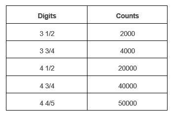
The number of counts usually applies to the DC volts function. Fewer counts may be displayed on the same instrument for certain functions. For instance, a 40,000-count DMM may be limited to 4,000 counts when measuring capacitance.
Resolution
Resolution is a measure of the smallest increment that may be discerned. At first glance, it would seem that 10.000 volts measured with a 40,000-count DMM would be read to a resolution of 0.001 volt. This is usually the case where the DMM’s A-to-D converter resolution exceeds that of the display, but some have less resolution than the display. In this case, the last digit could read 0, 1, 2, 3, 5 ,6, 7, 9, etc., with a linearly increasing voltage. Notice that only eight out of the 10 possible values were displayed. This is an artifact due to the digital nature of the conversion. In a more extreme case, only odd or even digits are displayed, hence the need for a resolution spec separate from the display count.
The increased resolution of 20,000- and 40,000-count DMMs does not come without penalties. Longer settling times are required for the far-right digits to reach their final value. To partially offset this, analog-like bar graphs are included. Because of their lower resolution, they provide near-instantaneous response to changing input signals. They permit peaking and nulling adjustment where rapid indication of the adjustment effects is needed.
The resolution specification for certain functions may be limited intentionally because of noise or accuracy limitations related to that particular function. The meaningless trailing display digits are usually blanked in such a situation. Capacitance is a good example of a function included in many high-end DMMs that has accuracy limitations; it is desirable to limit the display to only those digits which are meaningful. Displaying more than that has two fundamental problems. The first is that the meaningless digits usually are rapidly changing and would only serve to distract the user from those digits that are significant. Secondly, the display of random numbers leads the user to think that the instrument is inaccurate. Even if the reading appears stable, it may not be as accurate as with a 40,000-count DMM having 0.5% accuracy in AC volts. Additional resolution without a corresponding accuracy improvement is not meaningful to anyone except the advertising department!
Accuracy, Uncertainty, and Repeatability
Accuracy is often the differentiating specification between similar-appearing models. DC accuracy is most often used for the “banner” specification since it is usually better than the accuracy for other functions. DC accuracies of better than ±0.1% are just now becoming available. A specific number of counts (sometimes referred to as “digits”) will be added to the percentage figure due to rounding error and noise limitations. For DMMs, accuracy is specified as percent of reading as opposed to percent of full scale as specified for analog multimeters. If possible, avoid use of the bottom 10% or so of any range since accuracy is badly degraded there. It isn’t the percentage error that is the problem; it is the effect of the number of counts deviation being substantially larger in proportion to the measured value.
AC accuracy is usually less than that for DC. It is also optimized for 50 – 60Hz. Other frequencies may have poorer accuracy. As with DC accuracy specifications, a number of counts (often greater than for DC) will be added to the accuracy percentage. Also, for waveforms other than a pure sine wave, additional inaccuracy will be encountered when measured with an average-responding DMM. Even a true RMS-responding DMM will have some accuracy limitations for waveforms with high peak amplitude components if measured near full scale. This will be discussed further under TRMS/AVG.
From a metrologist’s standpoint, what appears in the manufacturer’s specification sheet under accuracy is more properly deemed uncertainty with accuracy being reserved to indicate the probability of the reading being accurate. A specification of 1% uncertainty would have an accuracy of 99%. Common practice among instrument manufacturers is to use the term “accuracy” and for calibration labs to use “uncertainty,” with both representing the same thing in real life.
Repeatability is often more important than absolute accuracy when making a series of measurements. You want the DMM to read the same value each time a measurement is made of exactly the same value. Repeatability is not usually specified directly but a limit is implied by the accuracy specification, since it must always be within the specified accuracy. It may or may not be considerably better than the specified accuracy and can vary considerably from one DMM to another, even those of the same model from the same manufacturer. Component aging, battery condition, temperature, and warm-up time may all affect repeatability to some degree. The only way to get a feel for a particular DMM’s repeatability is to make a large number of measurements of a precision source under a variety of conditions. The source should have better than four times the rated accuracy of the DMM to be able to sort out repeatability and accuracy limitations.
Calibration
In the past, calibration of DMMs has usually been accomplished by adjusting several internal “tweaks.” Initial calibration by the manufacturer included those along with filing or applying solder to the high-current range shunt resistor (actually a piece of buswire) to adjust its value. This was the Stone Age version of the laser-trimming process used for film resistors. These manual adjustments are gradually being displaced by software calibrations stored in the microprocessor. These software tweaks are accessible through a particular keystroke sequence while a specified input signal is applied to the DMM input. This technique reduces time and cost for calibration and allows better accuracy than attainable with a potentiometer or resistor adjustment since both solder and Cermet potentiometers have undesirable temperature coefficients.
TRMS/AVG
True RMS- or TRMS-reading DMMs populate the high end of available handheld instruments. They are assuming greater importance today in light of the heightened concern over power-line harmonic distortion caused by widespread use of switching power supplies in office computers and the proliferation of electronic devices. TRMS is an advantage when measurements of AC waveforms, other than sinousoidal, are required.
RMS measurements are a measure of the equivalent heating effect produced by a voltage and, to be accurate, must include any DC component present along with the AC component that most users associate with RMS readings. Many TRMS DMMs are not capable of measuring the TRMS value of the combined AC+DC and errors may result if there is any DC superimposed on the AC voltage.
Conventional non-TRMS DMMs measure the average of the absolute value of AC voltage and are calibrated so that the readings are corrected to that of the RMS value for a sine wave. This works well, but errors occur if harmonics are present with the effect becoming progressively worse as the harmonic content increases. Table 2 shows the readings that would be obtained when average and TRMS-responding DMMs are used to measure sine, triangular, square, and pulse waveforms and DC.
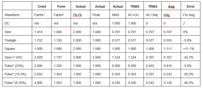
First, it can be seen from the data that average-responding DMMs can have a substantial error when measuring square waves with their rich harmonic content. TRMS is not always the best, especially if millivolt amplitude sine waves are to be measured. Average-responding instruments are faster settling to the final value or for adjusting levels near zero volts than equivalent TRMS DMMs and may have less offset or zero errors. This is common to TRMS meters since most use the same-type TRMS converter integrated circuit.
Second, a “TRMS” DMM that does not read AC+DC will exhibit a -42.2% error under the AC with DC offset condition shown in the table. In this case, if TRMS readings are required, it will be necessary to compute it from separate DC and TRMS AC measurements using the equation:
VTRMS = (VDC2 + VAC2)-2
In both of the previously described instances, understanding what the DMM is actually responding to will help to prevent misinterpretation of measurements. A few DMMs offer the ability to select average, AC TRMS, or AC+DC TRMS, thus allowing the user to choose the optimum mode for the desired measurement.
Crest Factor
Crest factor also should be considered when making AC voltage measurements of non-sinusoidal waveforms. Crest factor is defined as the ratio of the peak or “crest” voltage compared to the RMS voltage. The crest factor relates to ideal waveforms as shown in Table 2.
True RMS-reading DMMs will usually specify the maximum crest factor that they can handle accurately. This will usually be lowest near the full-scale reading due to the saturation characteristics of the TRMS converter chip. Better accuracy may be obtained near mid-scale.
Form Factor
Form factor is defined as the ratio of the RMS value to the average value and is the factor that when multiplied by the average value of a waveform will equal the RMS value.
Environmental
The environmental concerns for DMMs are primarily temperature, humidity, altitude, shock, and vibration. The operating temperature range is usually limited by the liquid crystal display. At low temperatures they become sluggish and hard to read. At high temperatures, contrast may degrade due to the change in optimum LCD operating voltage with temperature, especially when multiplexed. Exceeding the non-operating temperature range may result in permanent deformation of the LCD polarizer, particularly when combined with high humidity. After changing the temperature of a DMM significantly, 30 minutes or more should be allowed for it to stabilize to the new ambient temperature before making important readings. Also, examination of the accuracy specifications for DMMs will reveal an important fact – the specified accuracy is valid only for a relatively narrow range; 23±5°C and less than 70 or 80% relative humidity is common.
The versatility of the DMM and the design compromises required to allow additional features or optimization of certain specifications for advertising purposes require a thorough understanding of your DMM to achieve maximum accuracy and to apply it to problem solving in new applications.
To read this white paper in its entirety, including information on safety ratings and EMC, click here.
This article was contributed by Tektronix.