Power Contacts and Connectors Part I – What is Power?
Power Contacts and Connectors
Part I: What is Power?
Understanding power is critical to the design of power contacts and connectors. By presenting a six-part series exploring these specialty contacts, I hope to empower you to make the best design decisions the next time you embark on a project. We’ll begin by defining what is meant by a power application, and discuss current-related aspects of power applications. Obviously, applied voltage is also a power consideration, we’ll save that topic for another time.
Everyone would agree that a connector carrying 100 amperes is a power connector. But the current capacity of a conductor depends on its size. For example, a 25 mil/0.65mm square post has a typical current rating of three amperes. The current rating for a 22 AWG copper conductor, which has a comparable diameter (25.4 mils/0.654mm) in a power application, is 0.9 amperes. With post sizes decreasing to 15 mil/0.4mm, corresponding roughly to 26 AWG (15.9 mils/0.403mm), the corresponding conductor current rating is only 0.36 amperes! So, size matters, and current connector contacts are rated at power application levels.
It would be nice to have a metric defining power that was independent of size, and fortunately, such a metric exists. That metric is the T-rise of the conductor above the ambient temperature for a given current load. The most common metric is a 30-degree Celsius T-rise, and the equilibrium current that causes this T-rise is the current rating of the conductor or contact. (This T-rise value is used by Underwriters Laboratories, a standards organization addressing safety issues in electrical applications, and it has become a defacto standard for connectors. We’ll get into current rating later.) So, our metric for defining a power application is a 30-degree C T-rise.
Consider now the various factors that determine the T-rise of a contact or connector. The fundamental driving force is the Joule heating of a conductor or contact as it carries current. Joule heating is given by I2R, where I is the current and R is the resistance of the conductor. The effects of Joule heating, however, are moderated by thermal dissipation, primarily through conduction and convection, through and around the connector. Connector T-rise measurements, therefore, are dependent on a number of parameters, as will be discussed in a following article.
Remember that there are three sources of resistance in a contact spring, as indicated in the following equation:
Roverall = RPermConn + RBulk + RInterface
where Roverall is the overall resistance across a mated connector, RPermConn is the resistance of the two permanent connections, RBulk is the bulk resistance of the plug and receptacle contact springs, and RInterface is the resistance of the separable interface of the connector. The relative contributions of these resistances for a 25 mil square post connector system are of the order of 20 milliohms, less than a milliohm, 18 milliohms, and around one milliohm. The bulk resistances are dependent on the contact spring material and the dimensions of the contact spring, and therefore, are constant. The permanent connection and interface resistances are variable, with the interface resistance being the most susceptible to degradation.
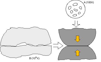
Figure 1 shows a schematic illustration of a separable contact interface at high magnification. The main point of the figure is to illustrate that, on the microscale of such contact interfaces, all surfaces are rough. This dictates that the contact interface itself will consist of a distribution of contact spots, called a-spots or asperities, rather than a full-area contact. This asperity structure is what gives rise to the contact interface resistance. The reduced contact area, consisting of a distribution of a-spots over some geometric area, depending on the geometry of the surfaces in contact, introduces a resistance—constriction resistance—that results from the current flow being constricted to flow through the individual a-spots. Constriction resistance can be reduced by increasing the contact area by various means, primarily the contact normal force, but never eliminated. A connector will always introduce some resistance to an electrical system. The prime objective of connector design, from this perspective, is to control both the magnitude and stability of the resistance that is introduced.
The difference in resistance between permanent connections and the separable contact interface is that permanent connections can support larger deformations, yielding larger contact areas, thus, lower resistances. The deformation of separable interfaces is limited by connector durability and mating force constraints to much lower contact forces, and therefore, smaller contact areas. The smaller contact areas, in turn, result in higher resistances, and lower mechanical and electrical stability, than that of permanent connections. For these reasons, our focus will be on how this a-spot microstructure of the separable interface determines a number of power application performance parameters.
Referring back to Figure 1, it is clear that current flow can only occur through those asperities that happen to be in contact. Recall also that these asperities are very small. That means that the resistance of individual asperities will be relatively high, compared to the contact interface resistance as a whole, and they will also be very responsive thermally. High asperity resistance and rapid thermal response means that the asperities will heat up very rapidly, resulting in high asperity temperatures. The temperature of the asperities (all asperities are at the same temperature) is given the name Supertemperature, TS. It must be noted that TS does not contribute to bulk heating because of the small asperity volume. The temperature is high, but the heat content is low. Thus, TS does not contribute to T-rise, at least until the interface melts. This is a significant point in that it indicates that TS is a factor in the capability of a contact interface to support transient currents, which, depending on the application, can be significant multiples of the rated current of the connector.
T-rise is determined primarily by the bulk resistance—RBulk—of the contact springs. As mentioned, RBulk is determined by the resistivity of the contact material and the geometry of the contact spring. To minimize T-rise, and thus, maximize the current rating, RBulk must be minimized. This is, of course, why power contact and connectors generally use high-conductivity copper alloys in their contact springs. For example, for a given contact geometry, a change from cartridge brass, C26000, which has a conductivity of 26 percent IACS (International Annealed Copper Standard), to C195, with a conductivity of 50 percent IACS, will double the conductivity, or halve the bulk resistance of the contact spring with a corresponding increase in the current rating of the contact.
A similar effect occurs with Supertemperature. It can be shown that TS is proportional to the square of the contact interface voltage drop, which is given by RInterface. RInterface, in turn, is proportional to the resistivity of the contact spring material. So the change in TS as a function of the contact spring material is proportional to the square of the change in contact spring material resistivity. Thus, the use of higher conductivity spring materials in power contacts increases both the current rating of the contact and its ability to support transient currents.
The next article in this series will review transient, overload, and steady-state currents and how they impact the current rating of a contact/connector.
- Nanocrystalline Silver Alloy Contact Finishes in Electronic Applications - April 6, 2015
- Nanocrystalline Silver Contact Platings - March 16, 2015
- Dr. Bob on Gold Flash Contact Finishes (and Max Peel) - September 22, 2014


