Five Attributes for High-Quality Wire Bonding in Glass-to-Metal Seal Terminals
Achieving a controlled finished surface suitable for wire bonding is essential for mission-critical applications. Here are the qualities you should look for.
By Sussex Wire, Inc.
Wire-bonded glass-to-metal and ceramic-to-metal hermetic assemblies are extensively employed in commercial, industrial, and mission-critical energy, military/aerospace, automotive, and medical applications. Products cover a wide range of assemblies, including vacuum feedthroughs, sealed relays, thermal sensors, pin feedthrough terminals, LEDs, beamline feedthroughs and injector tubes, dual in-line package (DIP) headers, thrust reverser control units, smart contactors, AC/DC power distribution assemblies, thermocouple feedthroughs, time delay devices, and ceramic packages of electronic components. The more critical the mission, the less room for error and ultimate failure.
When specifying connectors for these types of applications, it is important to identify the pin or terminal configurations, sealing materials, and finishes necessary to achieve wire bonds with excellent electrical conductivity. Many of the features of wire-bondable pins can only be accomplished by cold forming. Stamping and shearing, for example, will often distort the part geometry, making for an inferior contact surface. However, even cold-formed pins can have flaws. Achieving perfect parts requires significant skill and attention from both tooling designers and manufacturers, as well as a reliable and consistent quality program.
Here are five part and finish attributes of high-quality wire bond applications:
- Pin finish should be consistent across the entire target surface.
- Pin finish should be smooth with no pockmarks, ridges, or laminated striations interrupting the surface finish.
- Pin finish should cover the entire surface area across the wire bond target area. For example, the target area on the circular surfaces at the end of a terminal wires should be 100% of the theoretical circle, with no edge break, and sharp edges should be present to offer up to 100% of the surface as the target for wire bonding.
- No burrs that could potentially project from the wire bond area should exist anywhere on the pin.
- Cored or bi-metal terminals, such as the pins pictured in Example 3 (below), should have no separation or voids between the outer diameter material (e.g., Kovar) and the inner core (e.g., copper), as the wire bond surface must be consistent across both materials.
Below are several examples of hermetic seal assembly parts that illustrate both positive attributes and flaws to look out for.
Example 1: Terminal Pins for Hermetic Seal Applications
Pin Diameter: 0.018” (0.46mm) ±0.0003” (0.008mm)
Pin Material: Glass sealing Alloy 52
End Condition #1: Spherical radius
End Condition #2: Flat, wire bondable surface
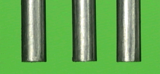
Figure 1: Side view of 0.018” pins showing well-formed sharp edges and corners
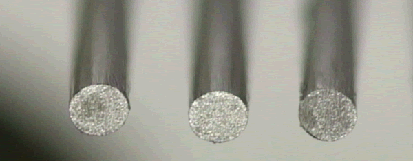
Figure 2: 45° view of the wire bond end of 0.018” pins showing perfectly formed, flat, and evenly finished sharp edges ideal for bonding
Example 2: Terminal Pins for Hermetic Seal Applications Using Bi-metal, Copper-Cored Wire
Pin Diameter: 0.04” (1.02mm) ±0.0003” (0.008mm)
Pin Material: Copper-cored nickel alloy (Alloy 52 per ASTM F30)
End Condition #1: Radiused
End Condition #2: Flat, wire bondable surface
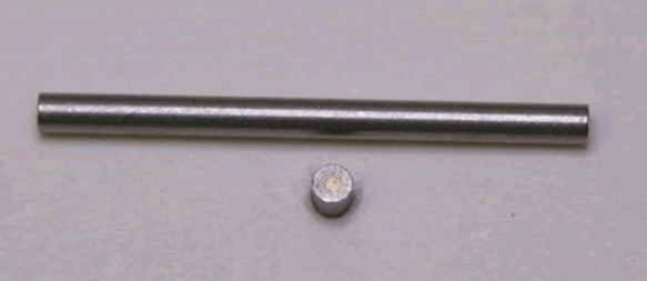
Figure 3: Side and head-on views of a cored, 0.04″ Alloy 52 pin, which show the sharp edges and the circular wire bond surface required for achieving a high-quality bond.
Example 3: A Comparison of Four Different Finishes on Bi-Metal, Copper-Cored Pins
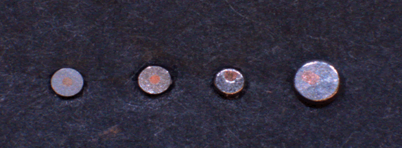
Figure 4: A comparative view of four different finishes on bi-metal, copper-cored pin surfaces (from left to right: A, B, C, and D).
Pin Surface A (Figure 4, far left)
Grade: Optimal
Qualities:
- The fine (RMS 20/Rz 3.1) finish goes across both the copper area and the nickel/iron (Alloy 52) sheath around the copper.
- The copper core is centered in the middle of the outer diameter (OD).
- The finish is consistent across the entire surface/on both the copper and the nickel/iron sheath.
- There is no pitting or separation between the copper and nickel/iron alloy.
- Since the wire-bondable surface is complete across the entire OD of the pin end, exhibiting no die roll-overs, burrs, or radiused/broken edges on the OD, the entire surface is available as a wire bond target.
Pin Surface B (Figure 4, second from left)
Grade: Very Good
Qualities:
- The finish (approximately RMS 30/Rz 4.7) is somewhat rougher than on Pin Surface A, but is otherwise identical.
- This finish can be maintained from lot to lot and serves as an example of common surface finishes that achieve very good results.
Pin Surface C (Figure 4, third from left)
Grade: Flawed
Qualities:
- This is the common shear-cut surface finish, which is normally the least desirable of all the finishes.
- The surface between the nickel alloy sheath and the copper center is uneven.
- There is a visible difference in surface finish appearance from the copper core to the nickel/iron (Alloy 52).
- This finish produces an inconsistent surface across the diameter, which may cause wire bonding issues.
- The copper core is distorted and somewhat off-center.
Pin Surface D (Figure 4, far right)
Grade: Flawed
Qualities:
- The top surface of this cold-formed pin has an off-center copper core with a distorted surface.
- There is a small difference between the surface finishes on the copper core and the nickel/iron (Alloy 52) OD. However, this slightly inconsistent surface finish is still an improvement over Pin Surface C.
Example 4: Very Small Diameter Terminal Pins for Hermetic Seal Applications
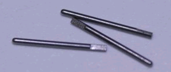
Figure 5: Three 0.015” diameter Kovar (nickel/cobalt alloy) RF pins with notched wire-bond ends.
These pins have a very small outer diameter (OD), 0.015” (0.38mm), and a fine, consistent surface finish that extends from the flat end of the pin, which also has a very sharp edge, down the OD, presenting a superior wire bond finish on all cut surfaces.
Interested in a specific market? Click a market below for current articles and news.
Automotive, Consumer, Industrial, Medical, Mil/Aero, Datacom/Telecom, and Transportation


