SMA RF Coaxial Connectors are Powerful and Versatile
The demand for SMA RF coaxial connectors has grown exponentially with the proliferation of wireless applications. We take a closer look at these connectors and the challenges they face in their quest to provide powerful data transmission.
A wide range of electromechanical solutions have evolved to facilitate board-to-board connections and power and data transmission. Versatile SMA RF coaxial connectors are one of the top choices for test and measurement, communications, broadcast, and wireless technologies.
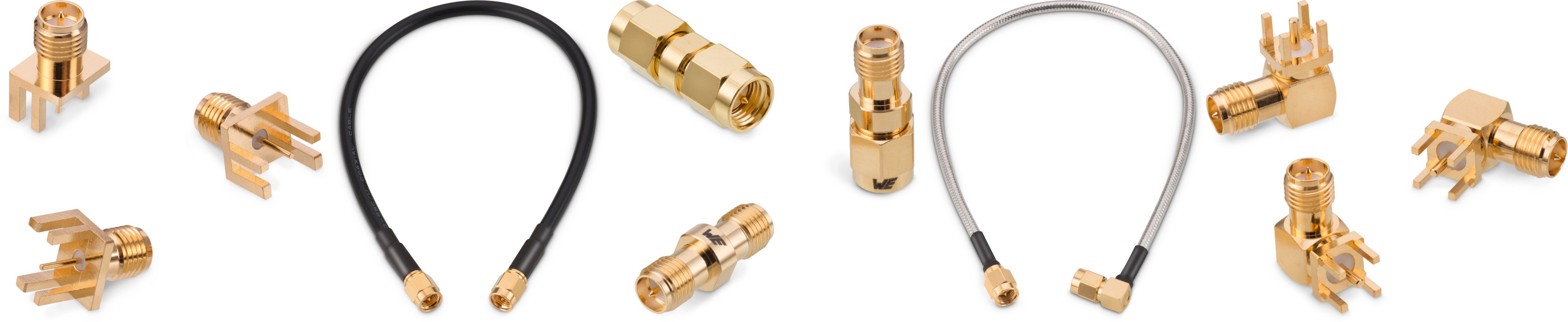
Selections from Würth Elektronik’s portfolio of SMA RF coaxial connectors, cable assemblies, and adapters.
For antenna applications, subminiature type-A (SMA) solutions that provide a bridge between radio frequency and microwave are available for both standard and reverse polarity. They are typically designed for a frequency range of DC to 18GHz with a characteristic impedance of 50Ω and have a threaded-type coupling mechanism that can achieve secure connections in even high-vibration environments.
The SMA product category ranges from standalone connectors to pre-assembled cable assemblies with adapters that allow for multiple standard SMA solutions for broad application suitability. Connector options include PCB- and panel-mounted options with right-angled or straight orientations, rear-mounted bulkhead and flange-mount options, and a number of termination styles based on the selected style.
Transmission efficiency is addressed by strengthening mechanical features in the connector. Many of the SMA RF coaxial connectors on the market use right-angle configurations as the primary reference point and aim to maintain the impedance at 50Ω. Due to the internal mechanical limitations, single-pin and soldered two-piece pin designs are the most widely used. Impedance mismatch can be caused by internal mechanical structure failure, dimensional imprecision, and improper solder paste volume at the solder joint of soldered two-piece designs. Würth Elektronik designs single-pin right-angled connectors to minimize the amount of signal loss caused at the bend.
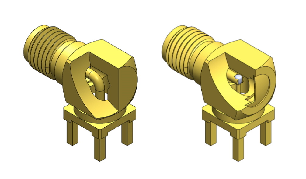
Single-pin (left) and soldered two-piece pin (right) SMA RF coaxial connector designs
Another consideration in right-angle SMA RF coaxial connector designs is the volume of air surrounding the contact since impedance mismatch commonly occurs at the bend of the center contact. In two-piece designs, the volume of air and PTFE must be precisely calculated in order to minimize impedance mismatch.
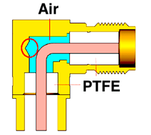
The volume of air surrounding the contact in a right-angle SMA RF coaxial connector has a direct effect on impedance mismatch.
The time-domain reflection (TDR) graph below shows the impedance on the two-piece soldered pin deviating away from 50Ω. This is usually caused by the solder paste at the joint point and/or an improper amount of air compensation due to poor internal designs.
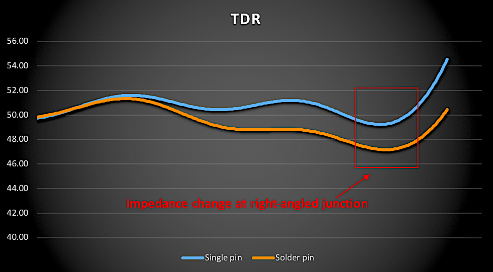
This time-domain reflection (TDR) comparison illustrates the discontinuities in single-pin and solder-pin center pin designs.
There are also several options for optimizing transmission lines with end launch connectors, including designs that accommodate various PCB thicknesses. These options offer different levels of mechanical stability, as well as impact the transmission line designed on the PCB. The contact area between the solder end of the center contact and the PCB transmission line is the key to both achieving good results in impedance matching and to getting good transmission. Higher frequencies are more easily achieved when there is a smaller impedance deviation in the contact area.
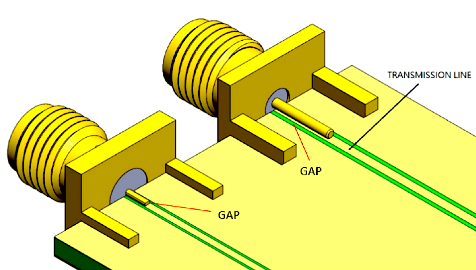
Larger gaps surrounding the round post pins can help compensate for impedance deviation to enable higher frequency performance.
To reach impedance matching at 50Ω, the transmission line on a PCB should ideally be designed with lower impedance to compensate for the increase of impedance at the contact area, where the solder end and transmission line meet. For frequencies above 6GHz, smaller and thinner flat pins can be used on transmission lines to lower the impact of impedance mismatch. In these types of high-frequency applications, a round post generally requires more effort to reach an acceptable impedance because of its mechanical structure. However, from a mechanical point of view, a round post is somewhat stronger than a flat pin, which could be more easily damaged during assembly and production process.
Standards and protocols including 3G, 4G LTE, 5G, Wi-Fi, Bluetooth, and other IoT communication systems are broadly employed in the consumer, medical, industrial, datacom, and telecom markets. SMA connectors are generally optimized for frequencies lower than 6GHz, which helps to account for their broad appeal. However, SMA connectors offered by Würth Elektronik can perform with frequency ranges extending from DC to 18GHz, providing product designers in these and other markets with increased design flexibility.
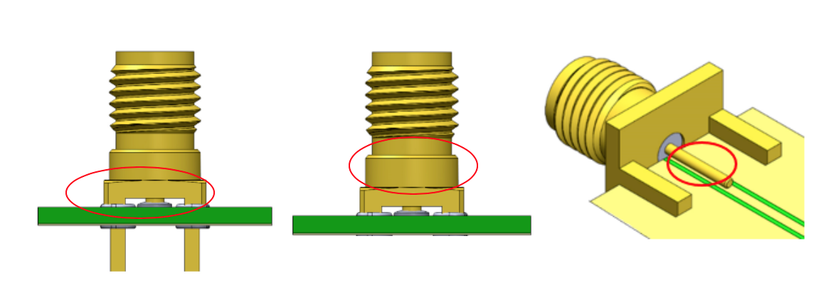
Impedance matching options for SMA RF coaxial connectors.
In addition to different pin and transmission line designs, customers can also achieve impedance matching by compensating for through-hole component length after they’re assembled on PCB (above left), controlling signal loss in the gap between PCB and SMT components (above center), and limiting the size and height of end launch connectors in transmission line designs (above right).
Applications that require the use of higher frequency SMA RF coaxial connectors face more difficulties in impedance matching at the design and test phases. Because the signal path between the connector and the PCB play a major role in reducing impedance mismatch, it is important to select the proper SMA connector and termination method early on. Technologies such as through-hole reflow mounting technology (THR) give designers additional options.
Pre-assembled coaxial cable assemblies are also offered for SMA-plug-to-SMA-plug and SMA-plug-to-SMA-bulkhead-jack connections, and with several different cable types ranging from flexible to hand-formable cables. Flexible coaxial cable options include RG-58C/U, RG-174/U, RG-142/U, RG-316/U, and RG-316 double braid, and hand-formable options include 0.141”, and 0.085” cables.
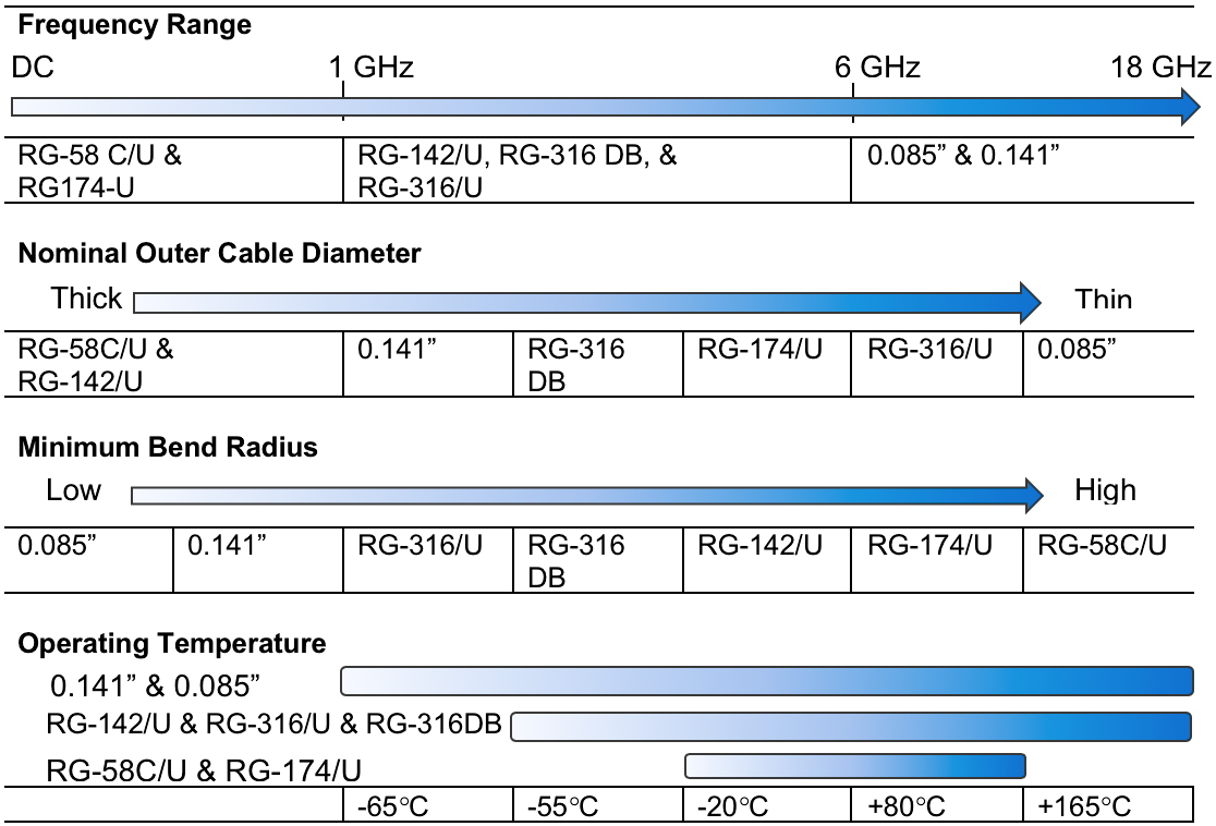
Characteristic performance for several coaxial cable options.
Connector manufacturers regularly release new SMA RF coaxial connectors in different sizes and with coupling mechanisms to meet the ever-evolving needs of device designers across the many markets that depend on these powerful and versatile connectors.
By Joyce Tseng, Division Manager, Coaxial Connectors, Würth Elektronik eiSos GmbH & Co. KG
For more information about RF coaxial connectors, visit Würth Elektronik online.
Like this article? Check out our other 2019 and Connector Basics articles.
Interested in a specific market? Click a market below for current articles and news.
Automotive, Consumer, Industrial, Medical, Mil/Aero, Datacom/Telecom, and Transportation
- Inside Device Connectivity: The Hidden Enabler of Software‑Defined Vehicles - July 14, 2026
- Bringing Modularity to Multi‑Board Systems - June 30, 2026
- Engineering’s Future is AI-Inspired, Human-Led - June 23, 2026