Connector Degradation Mechanisms—Corrosion Part I
Connector Basics: Connector Degradation Mechanisms—Corrosion Part I
This is the second article in a series on connector degradation mechanisms. Corrosion, in general terms, followed by a discussion of a particular corrosion mechanism, fretting corrosion, will be the focus of this piece.
Last month, we studied the asperity or a-spot model of a contact interface. In this continued discussion, it may be useful to refer again to Figures 1 and 2. To read the full article, click here. Take special note as you examine the asperity model: The asperity contact points are very small, of the order of microns in diameter. These points are distributed across an apparent contact area determined by the geometry of the contact springs at the interface and the contact force exerted by the springs, due to their deflection on mating. The electrical current across the contact interface must flow through the asperity contact points, resulting in a resistance called constriction resistance. The magnitude of the constriction resistance depends on the number, size, and distribution of the asperity contacts at the interface, because all the asperity contacts are in parallel, electrically. Constriction resistance exists even in the ideal case, when all the asperity contact interfaces are metal-to-metal, e.g. gold-to-gold or tin-to-tin. If any of the asperity interfaces are compromised by corrosion films or contaminants, the constriction resistance will increase. This is the reason why corrosion is a degradation mechanism for connectors. Loss of asperity contact area, or of asperity contacts, due to corrosion or contamination can result in contact interface resistance increases that are sufficient to lead to connector failures.
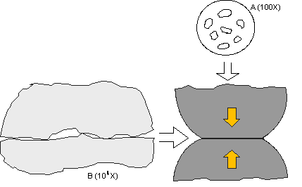 Figure 1: Schematic illustration of the structure of a contact interface resulting from
the intrinsic surface roughness on the microscale of the contact interface.
The kinetics of corrosion mechanisms in connectors can be very complex, but for the purposes of this discussion, two such mechanisms will be highlighted: surface corrosion and motion-induced corrosion, or fretting corrosion. Surface corrosion is a concern for all connector interfaces, even gold. It is important to note that the gold is not the source of corrosion products; rather it is the base metal of the contact spring, usually a copper alloy, that is the corrosion source. (Check back next month to learn more about corrosion effects on contact resistance in gold-plated connector systems.)
In motion-induced, or fretting corrosion, the term “fretting” refers to the small scale of a few, or up to a few tens of micron’s repetitive motions. Driving forces for fretting include vibration, mechanical and thermal shock, and thermal expansion mismatch due to temperature cycling. Those driving forces probably sound familiar, as they are the conditioning methods for a number of connector test specifications to assess the stability of connector contact resistance. Fretting corrosion is the predominant degradation mechanism for tin-plated connector systems. A discussion of the details of tin-to-tin contact interfaces helps us better understand the process.
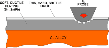 Figure 2: Schematic illustration of the structure of a tin surface.
Figure 2 schematically illustrates the important characteristics of tin surfaces as they relate to connector contact interfaces. Tin is a soft and ductile metal that always has a very hard, brittle, and thin oxide, of the order of a hundredth of a micron, on its surface. Tin oxide is a semiconductor, but the hard-over-soft structure of tin makes it very easy to disrupt and displace the tin oxide, so that direct tin-to-tin contact can result in a metal-to-metal and, thus, low-contact resistance. The mechanics of the displacement are simple. The tin oxide, being brittle and thin, cannot support an applied load, so the oxide cracks and the load transfers to the underlying soft and ductile tin. The tin flows under the applied load and the cracks in the oxide widen with the flowing tin extruding through the cracks to make contact to the surface applying the load. Thus, it is easy to establish a low resistance, metal-to-metal, contact interface between two tin-plated surfaces. The potential problem is maintaining the integrity of that interface under fretting conditions.
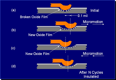 Figure 3: Schematic illustration of the kinetics of fretting corrosion.
Figure 3 schematically illustrates the kinetics of fretting corrosion of tin contact interfaces. The top figure shows the initial interface created as the tin oxide is displaced. At this point the electrical resistance of the interface will be of the order of a milliohm or so. If the contact interface moves, it experiences a fretting event as a result of any of the driving forces mentioned previously, and a new contact interface will be created in essentially the same manner as the original interface. This new contact will have a similar contact resistance. At the site of the original interface, the disrupted tin interface area will be exposed to air—specifically, to oxygen—and a new layer of tin oxide will form at all the original contact points. This is the corrosion part of fretting corrosion. If the fretting motions are repeated, each repetition will result in the formation of additional tin oxide debris in the general area of the contact interface. As this debris accumulates in and around the contact interface, it interferes with an increasing number of asperity contact spots and, eventually, the contact resistance of the interface will increase. The rate of resistance increase is dependent on many factors, the most important being the length of the fretting motion and the contact force. The importance of the length of motion is in its impact on the accumulation of oxide debris at the interface. Small motions produce a small amount of debris, but the debris remains at the contact interface. Longer motions may produce larger amounts of oxide debris, but the debris may be pushed towards the end of the fretting motion track, reducing the immediate impact of the debris on contact resistance. The effect of contact force is similar. Low forces will produce less wear, and, therefore, less oxide debris, but high forces will be more effective at displacing the oxide debris towards the ends of the fretting track. Needless to say, the geometry of the contact springs at the contact interface also plays an important role. The kinetics of fretting corrosion are complex indeed.
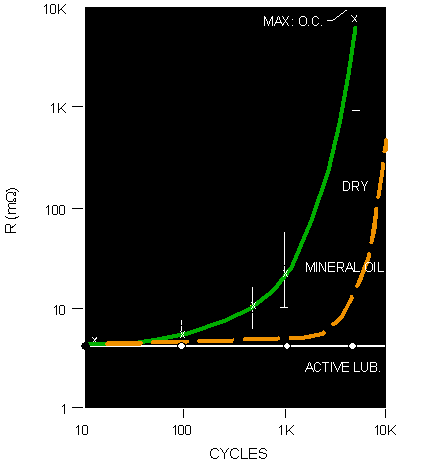 Figure 4: Schematic illustration of the relationship between contact resistance and fretting cycles.
Figure 4 schematically illustrates the general relationship between the average resistance increase due to fretting corrosion and the number of fretting cycles. The green curve is for a dry, non-lubricated tin interface. The rapid increase in resistance generally occurs at the order of a few thousand fretting cycles. The magnitude of resistance change can vary from tens of milliohms to ohms, and even open circuit. Two features, not shown explicitly in the graph, merit discussion. The first feature is the time dependence of fretting corrosion. That time is, of course, dependent on the rate of fretting cycles and fretting degradation kinetics. Suffice it to say that fretting corrosion can lead to resistance increases of the order of ohms, in tens of minutes under severe fretting conditions. Second, Figure 4 shows the average resistance, but that is not the whole story. If the contact resistance was continuously monitored at a high sampling rate, intermittent high resistance events would be noted before significant changes in average resistance would be recorded. The frequency of intermittents and the magnitude of the resistance change at each intermittent event would increase dramatically in the same manner as the average resistance as fretting corrosion continued.
OK, fretting corrosion as a degradation mechanism leading to contact resistance degradation is a real and significant performance issue for connectors. What can be done about it? There are two general approaches to fretting corrosion prevention: one directed at preventing fretting, and one at preventing corrosion.
Fretting motions can be prevented if the mechanical stability of the contact interface is sufficient to withstand the driving forces for fretting motion in the application environment of concern. The most effective means of providing mechanical stability is through high contact forces. High contact forces mean high friction forces at the contact interface to resist the driving forces for fretting motions. This is the reason that contact forces for tin connector systems are in the range of hundreds of grams, as compared to the hundred grams or less typical of gold connector systems. There are, however, limits to the magnitude of contact force that can be employed. The benefit of the friction force that comes with contact force in providing mechanical stability has a downside in that the same contact force also increases the mating force of the connector system. This effect may limit the number of positions that can be realized in a tin connector system. High contact forces also mean enhanced wear of the contact surface at the interface. As mentioned, tin is a soft material, and high contact forces will reduce the number of mating cycles the connector system can support before the tin is worn away. Recall also that high forces will enhance the rate of fretting debris formation, if fretting motions are not prevented. Thus, if the contact force is not sufficient to prevent fretting motions, the fretting degradation rate may be significantly increased.
Preventing the “corrosion” part of fretting corrosion is accomplished by using a contact lubricant. Contact lubricant is a generic term and includes lubricants that are intended to reduce friction, as well as lubricants to prevent fretting corrosion. It is important to specify to any lubricant supplier that an anti-fretting lubricant is desired to prevent the improper selection and application of lubricants. There are many formulations of anti-fretting contact lubricants available in various consistencies and with application processes designed to suit different operating conditions and applications. Properly formulated anti-fretting lubricants can be effective at reducing the potential for fretting corrosion. An example is the white curve, the “active lubricant,” in Figure 4. With this lubricant, the fretting cycling was carried out to 50,000 cycles with no significant degradation in contact resistance.
One concern with the use of contact lubricants is ensuring proper application of the lubricant, as well as confirming its presence on the product as received. If the lubricant is to be self-applied, the costs and possible environmental effects of the selected lubricant must be considered. An additional potential issue may arise in applications where the potential dust and/or contamination are high. Some contact lubricants may tend to be “tacky” and to retain dust with the dust itself then contributing to fretting degradation.
The major connector plating systems that are susceptible to fretting corrosion are tin and nickel. Flash gold systems may become susceptible to fretting corrosion if the flash gold is worn away due to fretting wear or the mating cycles of the connector and the nickel underplate is exposed.
- Nanocrystalline Silver Alloy Contact Finishes in Electronic Applications - April 6, 2015
- Nanocrystalline Silver Contact Platings - March 16, 2015
- Dr. Bob on Gold Flash Contact Finishes (and Max Peel) - September 22, 2014
