10 Key Strategies to Ensure Signal Integrity at High Data Speeds
Demand for bandwidth and design complexity are increasing as more sensors are connected to systems and more data need to be transmitted quickly, reliably, and securely. The priority is to ensure that a signal sent from A to B is not distorted.

Ensuring Signal Integrity
Ensuring signal integrity is critical for engineers who design data-heavy applications that rely on constant streams of accurate data, such as for the Internet of Things, Industry 4.0, and interconnected ecosystems. Above all, at high bit rates and over long distances, effects such as noise, distortion, insertion/return losses, and crosstalk may degrade electrical signals to the point where errors occur and a device or system fails.
For seamless connectivity, connector performance should be seen as just one part of the equation. Other key factors that determine data transmission success include the quality and performance of the cable itself, the interface between the connector cabling and connected devices, and the quality of the transmitter and receiver. Balanced cabling performance is defined by multiple parameters. The most relevant are attenuation (insertion loss), reflection (return loss), near-end crosstalk (NEXT), and far-end crosstalk (FEXT). In fact, every single decision in the design of a cable-connector assembly can ultimately affect signal integrity.
10 key design challenges must be overcome to optimize products for high-speed data transmission:
1) Transmission line
The loss of the cable connection affects signal transmission. The higher the signal frequencies, the stronger the loss. As the maximum required frequency (fMAX) of a signal goes high compared to the distance that it needs to travel, simplified lumped circuit models need to be replaced with their high-frequency counterparts, such as transmission line formulation or even full wave Maxwell’s equations. The DC connectivity of metallic surfaces can no longer guarantee high-speed connectivity.
2) Signal degradation
Reflection and attenuation are the two main mechanisms of signal degradation. Degradation can occur at the intersection of the transmitter and connector. If the input impedance of the transmitter is different from the input impedance of the connector, part of the input energy will reflect towards the transmitter. Some of the remaining energy will be lost in the connector due to metallic or dielectric loss, and the wave will reach the other side of the connector. While reflection is the most important mechanism of loss of signal at the connector, attenuation is the main mechanism of loss in the cable. Apart from these two effects, noise and crosstalk by other pairs can also cause problems.
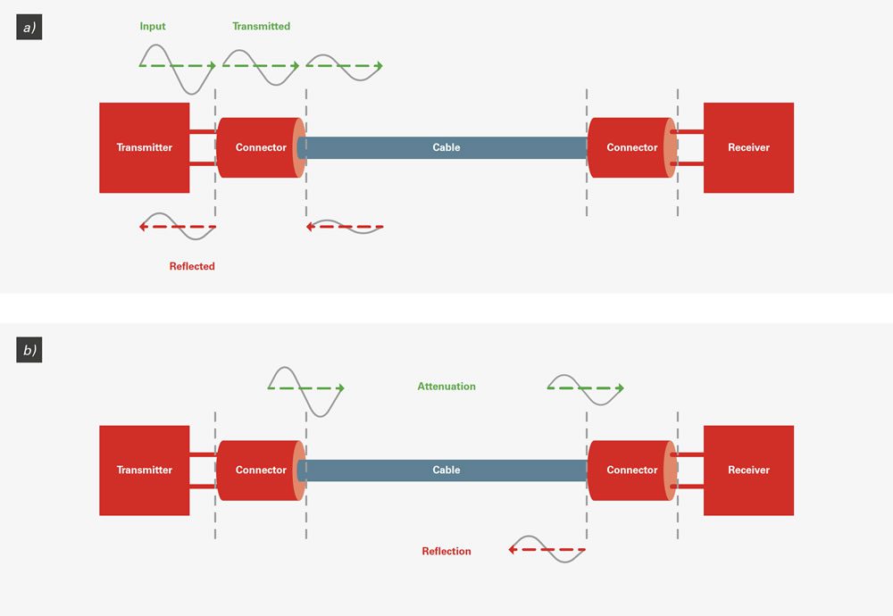
Signal degradation due to attenuation and impedance mismatch: a) on the transmitter side, b) on the cable and receiver side.
3) Impedance matching
To optimize impedance matching (ratio of V/I or E/H), factors such as diameter of contact, distance between contacts, contact form factor, and type of materials for all components should be considered. The design of a connector can affect NEXT and FEXT performances, and the connector must also be optimized against these constraints.
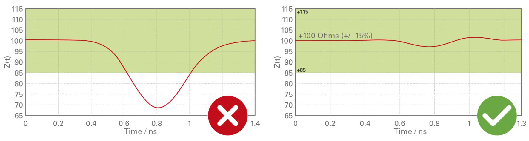
The differences between a connector without and with a design optimized for impedance matching.
4) Crosstalk
It is important to ascertain whether, and to what intensity, waves running in parallel channels interact with each other and cause interferences (crosstalk). One of the parameters for cable-connector assembly to achieve the usual bit error rate (BER) of 1e-12 tolerated in the physical layer, is the level of NEXT and FEXT crosstalk, i.e., the field coupling from one channel to the other one within a cable. To minimize crosstalk, both the location of pins and the attribution of signals to the pin layout are critical.
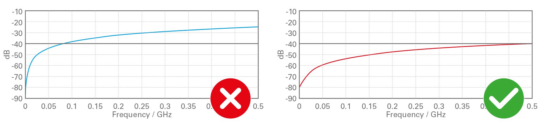
Comparison of two crosstalks with different ways of attributing signals in the same connector.
5) Vector Network Analyzer (VNA)
Data protocols provide the normative values of data transmission parameters (insertion loss, return loss, crosstalk, noise) to ensure the compatibility of the various components of a system – transmitter, receiver, cable, connector – so that they can function together appropriately. Typical protocols include Ethernet, USB, SDI, DP, and HDMI. Once a design has been optimized for a defined protocol, a physical connector-cable assembly prototype needs to be tested to validate the full characterization using a Vector Network Analyzer (VNA). This measures the wave parameters of the reflection and transmission at electrical connections of components as a function of frequency, the so-called scattering parameters, or S-parameters. Typical devices to be tested do not have coaxial interfaces, which are necessary to perform the measurement, so test fixtures often need to be inserted between an instrument’s coaxial interface and the device under test (DUT), such as a PCB, package, connector, or cable. To connect the cable-connector assembly to the VNA device, one needs to design a high-speed precision PCB based on the required bandwidth.
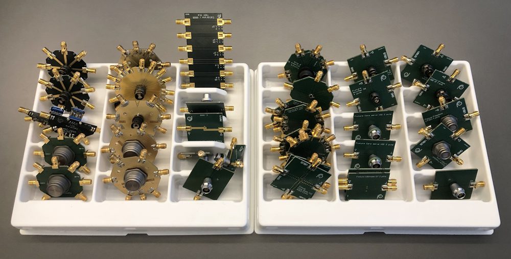
Examples of PCB fixtures for VNA measurement
6) Geometrical optimization
Any geometrical entities can potentially improve or disturb the flow of energy from one side of a connector to the other side. Hence, every high-speed related design must be cross-optimized for all aspects of mechanical, electrical, signal-integrity, and EMI/EMC performances. The main influential parameters to consider are connector design, cable length, cable performance (loss), and the controlled and repeatable cable assembly and potting processes above 1 Gb/s.
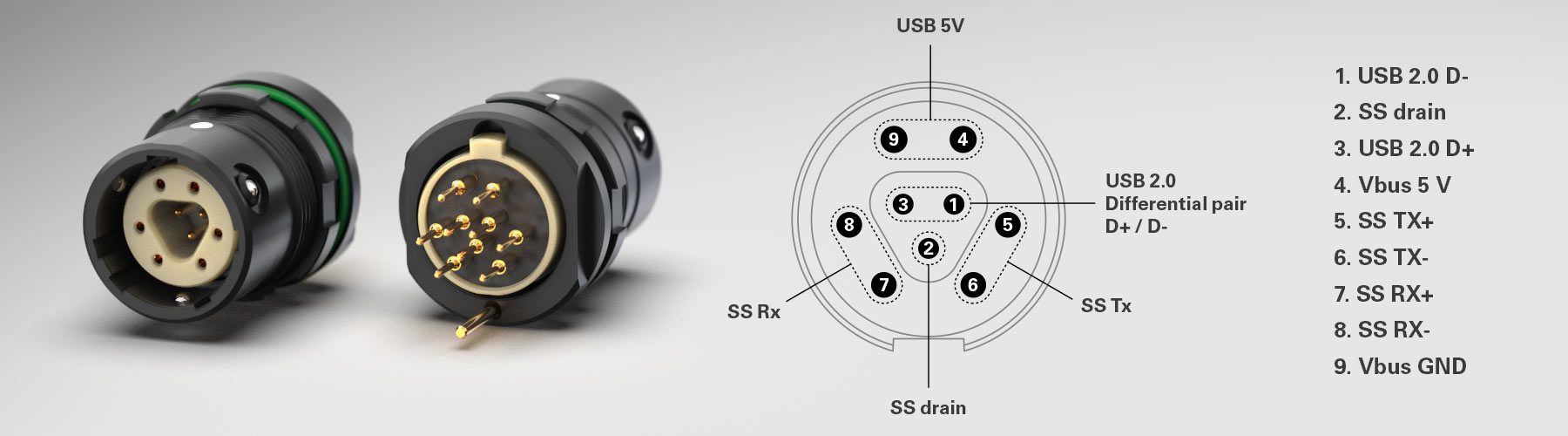
The Fischer MiniMax™ Series with nine contacts is an example of a connector that has been specifically designed to achieve high-speed data transfer using a single protocol (USB 3.2).
7) Impedance measurement
After ensuring mastery of the transverse electromagnetic (TEM) mode of propagation by observing the longitudinal field distribution, it is essential to make sure that pin diameters and their distributions are designed properly to achieve the right impedance. The design of a connector can affect NEXT and FEXT performances, and the connector must be optimized against these constraints as well. For impedance measurement, one can use a time domain reflectometry (TDR) device.
8) De-embedding
The effect of PCB fixtures must be removed from measurement results using de-embedding. It is recommended to implement the IEEE 370-2020 standard to ensure an optimal PCB manufacturing and de-embedding process.
9) SerDes simulation
The overall speed of a communication system on the physical layer depends on the physical layer’s architecture and the specifications of the transmitter and receiver. In many applications a special configuration of a communication link may deviate from specifications in the standards. System-level serializer/deserializer (SerDes) simulations are used to measure the data transmission rate of a cable-connector assembly. The simulations can be visually represented in an eye diagram, in which a superimposition of bits create an “eye” shape that provides insight into the system and crucial connection parameters at a glance. The diagram shows whether signal transmission is taking place at the required speed and how susceptible is it to interference.
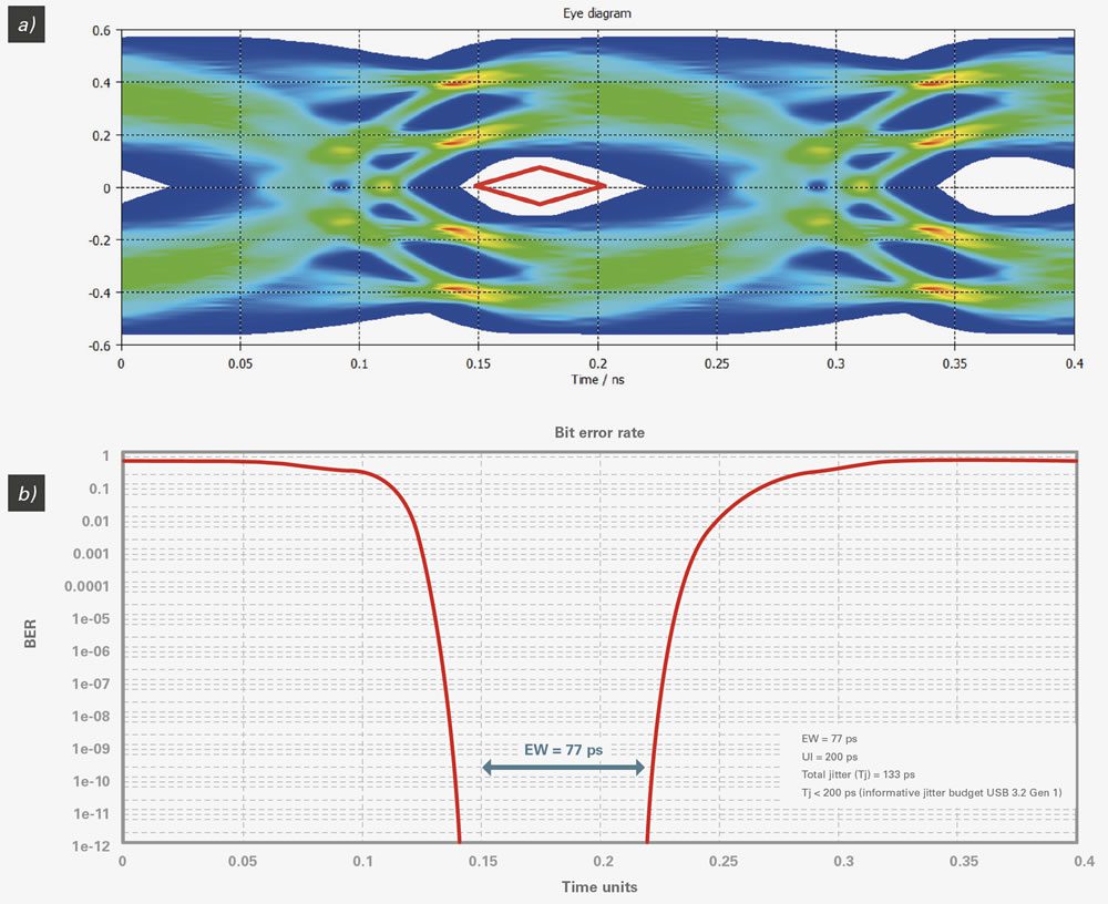
SerDes simulation of MiniMax link at 5 Gb/s: a) eye diagram illustrates minimum eye opening for USB 3.2 Gen 1, b) bathtub timing curve and jitter calculations at receiver ports.
10) Link optimization
There are numerous situations in which the channel eye diagram is closed. The eye can be opened by including signal conditioning techniques such as continuous time linear equalization (CTLE), decision feedback equalization (DFE), or other methods.
To optimize products for high-speed data transmission and prevent signal distortion, engineers should design for signal integrity from the outset. By taking a holistic approach to connectivity (from transmitter to receiver), the common pitfalls outlined above can be avoided. It is also necessary to thoroughly test the associated connection technology at both component and system level.
Visit Fischer Connectors, Data Transmission to learn more.
Like this article? Check out our other How to Specify, Cable and High-Speed articles, our Datacom Market Page, and our 2022 Article Archive.
Subscribe to our weekly e-newsletters, follow us on LinkedIn, Twitter, and Facebook, and check out our eBook archives for more applicable, expert-informed connectivity content.
- 10 Key Strategies to Ensure Signal Integrity at High Data Speeds - August 9, 2022