Testing Automotive Connectors
For the companies that make and supply them, testing automotive connectors is an important step in their design and production.

Electronics make up over 35% of the cost of a modern car, with tens of thousands of electronic components inside each vehicle. If any of them fail to withstand the harsh environmental conditions of the road, the consequences could be dire. This makes the stakes for durability, reliability, and accuracy quite high. From in-cabin applications, such as infotainment, to cameras and lidar outside the vehicle, to the engine and battery packs, which experience the harshest conditions, automotive connectors must meet strict specifications to maximize safety and performance. For the companies that make and supply them, testing automotive connectors is an important step in their design and production.
Two main automotive specification authorities are USCAR in the United States and LV214 in Europe. USCAR (United States Council for Automotive Research) is a collaboration of Ford Motor Company, General Motors, and Stellantis. LV214 is the German automotive test standard developed by Audi, BMW, Daimler, Porsche, and Volkswagen.
USCAR and LV214 standards specify which tests each component must pass. The testing should be completed by an independent and accredited testing organization. Many environmental tests are included in the standards, such as random vibration, salt spray, moist heat cycling, retention force, or dimensional accuracy.
“USCAR and LV214 specify testing parameters in extreme detail in order to standardize testing for connectors,” said Kerrick Klancnik, sales engineer – automotive, at Hirose Electric. “As a Japanese company, Hirose doesn’t necessarily standardize our testing to match U.S. or European standards. We have our own testing and detail out how it’s performed and how it compares to the other standards. That is typical of other Asian companies, as well.”
Klancnik explained the various tests as follows.
Temperature and vibration
As different areas of a vehicle exhibit different temperatures, USCAR specifies five temperature classes for components. To ensure safety, components are tested by thermal cycling, high temperature humidity cycling, and high temperature exposure.
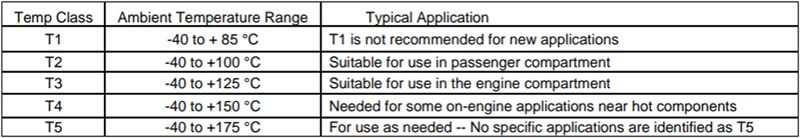
Table 5.1.4.1 from USCAR-2 rev8 specifies component temperature classes.
The thermal cycling test involves putting a sample in a cold chamber at the minimum temperature (-40 °C in this case) for 30 minutes, then quickly transferring the sample to a hot chamber at the maximum temperature (85 °C for T1) for 30 minutes. This cycle is completed 100 times for each sample.
In the high temperature humidity cycling test, the sample is brought to the minimum temperature and uncontrolled humidity, then up to 85 °C and 80-100% humidity for four hours, and then up to the maximum temperature and 80-100% humidity for two hours. This cycle is completed 40 times for each sample.
The high temperature exposure test involves putting each sample in the hot chamber at maximum temperature for 1,008 hours.
Vibration and Shock
Vibration can cause wear of the terminal interfaces, intermittent electrical contact, and mechanical failure of connector housings. USCAR classifies vibration intensity into five levels. Most internal connectors need to be tested to V1 “chassis profile,” while many external connectors will require V2 “engine profile” testing. V3 and V4 vibration profiles require thermal cycling during the vibration test. All vibration profiles are significantly harsher than vibration testing performed on components for typical consumer or industrial usage.
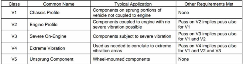
Table 5.1.4.3 from USCAR-2 rev8 specifies component vibration classes.
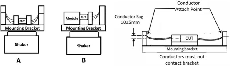
USCAR figure 5.4.6.3A and 5.4.6.3B illustrate the setup used to test random vibration.
For V1 or V2, using the setup shown above, the connector is subjected to random vibration for eight hours on each axis, or 24 hours total. The root mean squared acceleration (rms) is 1.81g for V1 and 12.1g for V2.
Shock testing is completed using the same setup. For V1 and V2, samples are subjected to 35g acceleration in one direction in 5-10 milliseconds. This is then repeated 10 times per axis. For V3-V5, samples are subjected to 25g in one direction for 15 ms, then 100g in the other direction for 11 ms.
Retention Force
A wire-to-board connector has the potential to break in three places if it is yanked apart. One is where the connector is soldered to the PCB. In general, more solder allows greater retention. A second point is where the receptacle plugs into the header. This part is usually dependent on the strength of a plastic latch. The third point is where the wire is attached to the crimp socket. This becomes more important for connectors with only one or two wires. If there are 20 wires and all are pulled equally, they are not likely to come out of their crimp socket.
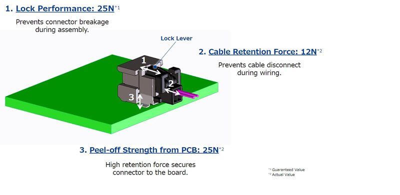
This diagram of Hirose GT50, an ultra-small wire-to-board connector, illustrates the three places a wire-to-board connector is vulnerable to breaking.
Mating cycle testing
Different connector applications require different numbers of mating cycles. If a connector will need to be mated and unmated many times, the connector design will need to change to accommodate this, usually by adding additional plating to the terminals. In testing, the contact resistance of a connector sample is measured as it is mated and unmated. As the mating cycles increase, the contact resistance will also increase. Depending on the connector application, a maximum allowable contact resistance will be identified, and a corresponding maximum number of mating cycles will be achievable by the connector.
Visual Inspection
After each test, all tested samples must be inspected at 10x magnification, looking for evidence of deterioration, deformities, cracks, excessive plating wear, swelling, corrosion, discoloration, or other issues that could affect functionality.
“All the tests mentioned are concerned with connector accuracy, rather than precision. While it is important that components can survive harsh conditions, it is also important that every piece is manufactured to be just as durable as the initial samples that are tested,” said Klancnik. “To maintain perfect quality from the first piece to the millionth piece, Hirose inspects every connector that comes off the production line.”
Visit the Preferred Supplier page for Hirose Electric to learn more about the company and its products.
Like this article? Check out our other articles on High Reliability, our Automotive Market Page, and our 2023 and 2022 Article Archive.
Subscribe to our weekly e-newsletters, follow us on LinkedIn, Twitter, and Facebook, and check out our eBook archives for more applicable, expert-informed connectivity content.
- Three Companies, One Mission: Reduce Plastics in Electronic Connectors - July 28, 2026
- Cable Accessories and Tools Product Roundup - July 28, 2026
- Extreme Temperature Innovations for Aerospace and Defense - July 21, 2026