Solder-less, Spring-Loaded Coax Connector Revolutionizes RF Connectivity
For decades, the subminiature push-on connector has been a mainstay of RF applications. However, in complex architectures, the SMP interface had challenges in blind mating situations. A solderless coax connector presents an alternative.

Article Contributed by Smiths Interconnect
The landscape of high-speed radio frequency (RF) interconnects is continuously evolving, driven by the need for enhanced performance, simplified assembly, and improved durability. Since its introduction in the 1980s, the subminiature push-on (SMP) connector, initially marketed as GPO, has been a staple in many RF applications. SMPs are typically a three-piece system, featuring two male connectors, referred to as shrouds, which are designed to be surface mount or through-hole soldered to printed circuit boards. They come in two types: detent and smooth bore. The third piece, a female connector, is referred to as a bullet and completes the mating of the two male connectors located on adjacent PCBs.
Traditional SMPs are usually robust RF contacts capable of operating from DC to 40 GHz with low insertion loss. They are designed for a nominal 50 Ohms impedance, operate between −65 °C and 165 °C and exhibit good leakage characteristics, offering better than −60 dB rejection. While SMPs can be blind-mated, this often presents challenges due to the potential for misalignment and the high forces required. Mating a single SMP connector can require up to 9 lbs of force. For a PCB assembly with 32 connectors, for instance, the total mating force would exceed 280 lbs.
A solder-less solution
Smiths Interconnect has introduced a new single-piece, spring-loaded coaxial connector designed for high-speed RF applications. EZiCoax features a double-ended design with a spring-loaded signal and ground contact, fully encapsulated within the assembly. It mates between two PCBs by compression, eliminating the need for any soldering. This solderless interface is designed to be supplied in an interposer — a frame that aligns the contacts precisely to the PCB. A significant benefit is that interposers can be highly customized and can incorporate both digital and power contacts alongside the coax, providing a comprehensive solution for mixed-signal applications. The smallest coax offers a low profile, with a 3.30 mm board-to-board distance and can be used on a pitch as small as 3 mm.
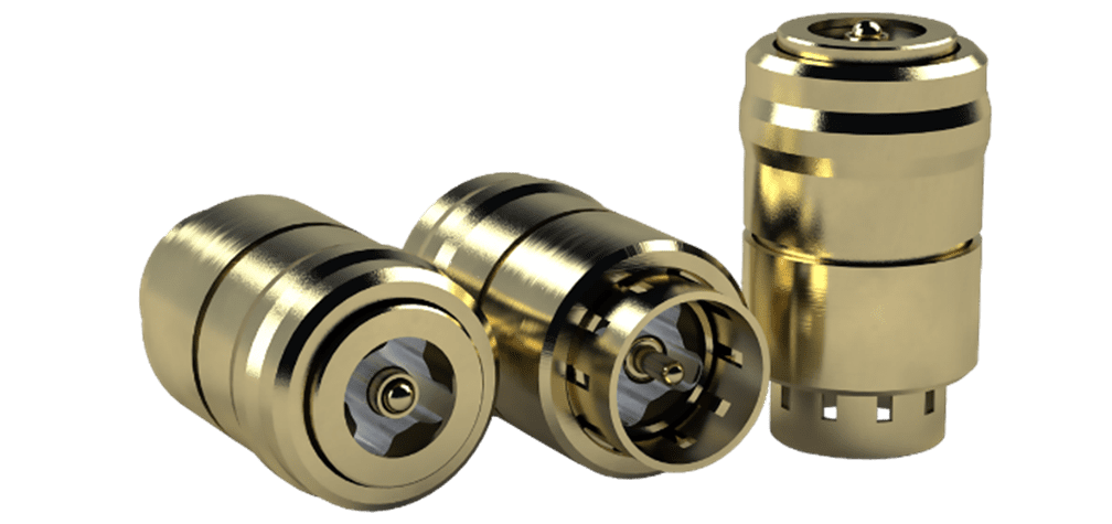
Smiths Interconnect’s EZiCoax is a solderless 50 Ohm RF contact that performs to 40 GHz. Qualified to ESCC 3402 ESA Space qualification, highlights include random vibration of 53.79 Gs and mechanical shock of 100 Gs half sine in shock and vibration tests repeated three times in all three axes.
Misalignment tolerance
With traditional SMP-style connectors, board-to-board tolerances and shroud placement can lead to three types of misalignments:
- Radial misalignment occurs when the shrouds are offset from true centre in the X, Y, or both directions.
- Axial misalignment is the distance variation (in the Z-direction) between the two PCBs.
- Angular misalignment is a product of both radial and axial misalignment, causing the bullet to sit at an angle within the shroud.
The EZiCoax was designed to perform even under misalignment, to protect system reliability, by designing the PCB to the recommended pad layout, which specifies a 26mil signal pad with a 41mil anti-pad. In tests under axial misalignment, the performance remains strong, with insertion loss at the maximum working height of 0.138 inches (3.5 mm) dropping only to about −1.1dB of attenuation.
With radial misalignment, performance also remains highly stable. There is less than a half dB shift in insertion loss with a mismatch of ±10 mils (0.25 mm) in the X and Y directions.
Since interposers are designed to ensure the PCBs are flush-mounted and parallel, angular misalignment is minimized. If it does occur, the design allows for up to 2.5 degrees of displacement with less than −1 dB of loss.
Interposer solutions and applications
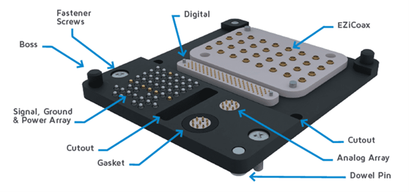 An interposer is an electrical interface that routes connections between one socket/connection and another, essentially bridging two opposing sides of a PCB. The housings are typically made of engineered plastics like TECAPEEK or Ultem, though other materials may be used for specific environmental or electrical needs.
Interposer designs can incorporate various features: dowel pins or bosses for precise alignment, thru-holes and hardware for securing the assembly, as well as custom features like cutouts to avoid existing system components and the ability to integrate environmental or electromagnetic interference (EMI) gasketing.
EZiCoax is an improved alternative to older methods of passing RF signals in interposers, with arrays that typically require a grounded housing and take up considerably more space on the board. This is especially significant for space and military applications, which demand high performance and ruggedness while benefiting significantly from ease of installation and upgrading.
In applications like satellites, deep space probes/rovers, HTCS antennas, launch vehicle avionics, telemetry modules, as well as the active electronically scanning arrays (AESA) radar systems used in defense, EZiCoax can replace current RF interconnects and offers the possibility of 90% weight saving, easier assembly, extremely reliable performance with an overall lower cost of ownership.
Traditional SMPs require a complex, multi-step process involving soldering of the shrouds, specialized tools for installation/removal, post-soldering flux cleaning, and regular inspection of the soldered joints. EZiCoax utilizes compression mounting and alignment via the interposer features, making assembly quick and the connection reliable. Furthermore, the spring-loaded technology improves product life and reworkability; it requires only a low mating force and no extraction force for de-mating, allowing the interposer to be assembled and removed repeatedly without the risk of PCB damage associated with the high forces of SMPs. This solderless alternative provides reliability by absorbing greater misalignment, tolerating up to 0.25 mm of axial and 0.33 mm of radial misalignments.
Learn more at Smiths Interconnect.
Like this article? Check out our other RF and Coax articles, our Military and Aerospace Market Page and our 2025 and 2026 Article Archives.
Subscribe to our weekly e-newsletters, follow us on LinkedIn, Twitter, and Facebook, and check out our eBook archives for more applicable, expert-informed connectivity content.