How to Specify High-Speed Backplane Connectors
FCI’s Stephen Smith explains how to specify high-speed backplane connectors so your system will work now as serial data rates increase to beyond 25Gb/s, as well as into the future.
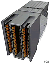
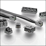
FCI’s ExaMAX high-speed connectors are designed to deliver 25Gb/s electrical performance while offering a migration path to 40Gb/s.
Despite the dire predictions of folks in the optical camp, armies of copper users continue to design systems that can transmit information at data rates that were unheard of as little as five to 10 years ago. When designing a copper backplane or midplane system, the size, shape, and PCB footprint of the high-speed connector dictates much of the design, and many considerations enter into the connector selection process.
Mandatory Requirements
Some connector requirements are mandatory, such as the need to be qualified to the Telcordia GR-1217-CORE Central Office (CO) Specification. To meet the rigors of that spec, high-speed backplane connectors typically must possess two points of contact in the separable mating interface. Another obvious mandatory requirement is sufficient robustness to survive and function when mounted on heavy PCBs, which are sometimes installed into a rack chassis with a less-than-gentle touch.
System Architecture
After the mandatory requirements for the connector are defined, there still exist many discretionary decisions to be made. Some of the earliest of these involve determining the system architecture. Will it be a traditional backplane with daughtercards on one side only that utilizes right-angle connectors? Or will it be a midplane with daughtercards on both sides of the board? Will it be an orthogonal midplane with daughtercards oriented vertically on one side of the midplane and horizontally on the other? One of the newest options is a direct-attach orthogonal configuration where the daughtercards connect directly to each other without any connection to the midplane. The high-speed signals pass through the missing center of a picture-frame-like midplane with only low-speed or power-making connections to the midplane around the perimeter.
How Many Differential Pairs?
Since space is always at a premium, the designer should determine how many differential pairs need to fit into the available space. This simultaneously dictates both the connector size and signal density. The designer must decide which “equipment practice” to employ. One of the most common today is the Hard Metric Standard which standardizes features in metric units such as the dimension of 12.5mm between the edge of the daughtercard and the surface of the backplane. Of course, other equipment practices exist, such as those that are specific to individual connector vendors.
Insertion Loss, Return Loss, and Crosstalk Performance
But ultimately, the connector must be able to carry signals at today’s data rates as well as those to which the system will be upgraded in the future. Hence, it must have excellent insertion loss, return loss, and crosstalk performance. For speeds of 25Gb/s and higher, each of these metrics should exhibit excellent performance up to at least the Nyquist frequency of the signal, which would be 12.5-12.8 GHz for NRZ modulation at 25Gb/s. Such a connector would work at a future data rate of 56Gb/s with PAM4 modulation. To assure successful operation at future data rates, designers should select a connector that avoids the problems of previous-generation products such as insertion loss roll-off due to the presence of stubs in the mating interface.
Technical Support
Finally, in addition to all of the above-mentioned physical requirements, some people consider the “‘soft” requirement of how well the connector vendor is able to provide technical support both before and after the sale. Some connector vendors offer both mechanical and electrical design assistance, including but not limited to providing customized product performance reports, assistance in laying out boards, help with chassis design, and the modeling of channels to ascertain their signal integrity performance at the data rates of today and those of the future.
[hr]
Stephen Smith is senior staff signal integrity engineer at FCI.
