How to Specify Connectors for LED Applications
Connectors play a variety of roles in LED lighting systems. Here, Mill-Max looks at headers and sockets used in coplanar board mating, providing a complete guide on how to specify connectors for LED applications.
 Connectors play a variety of roles in LED lighting systems, depending on the application. In many cases, they provide the electrical connection to the LED driver boards or the mechanical support for the LEDs. A variety of connectors can be used in these applications ranging from board-to-board connectors to bulb sockets and receptacles. Here, we look at board-to-board connectors (headers and sockets) used in coplanar board mating, as well as receptacles and sockets for bi-pin LED bulbs such as MR11 and MR16 styles.
In both these applications, designers should look for connectors that provide a variety of options that meet budgets and multiple design configurations. Look for flexibility in coplanar board-mating connectors. LED lighting applications, such as strip lights, typically require end-to-end mating or daisy-chaining of boards via coplanar board-mating connectors. Designers should look for solutions that offer a variety of board-mounting options to meet requirements for both surface-mount and thru-hole components, which enable the same product line to be used across multiple applications. These options also provide the designer with several ways to daisy-chain or connect the boards in their LED lighting systems. In some cases, applications will use all surface-mount components, and in others, they will use mixed surface-mount and thru-hole technologies.
Designers need to answer several questions before they select the connectors for their applications:
- Which assembly process are they using — surface-mount, thru-hole, or mixed technologies? How much board real estate do they have, and how much height off the board is available?
- How reliable and robust do they need the connections to be?
- Is cost the major factor in the design?
Once these questions are answered, designers can look at the connector options available to daisy-chain the boards together in series. For example, horizontal surface-mount connectors with two different pitch options (0.050 inches on the left and 0.100 inches on the right), as shown in Figure 1, takes board real estate into consideration. Designers may require a finer-pitch connector to save on board space.
The key benefit of the surface-mount header and socket option is to allow the designer to plug and unplug the boards as needed, which can simplify the assembly process. In some cases, it’s necessary to disconnect the boards, particularly if a new board needs to be plugged in due to a part or board failure.
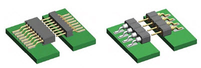
Figure 1: Mill-Max’s series of horizontal surface-mount connectors offers two different pitches (0.050″ on the left and 0.100″ on the right) for greater design flexibility in space-constrained applications.
Figure 2 shows another version of the horizontal surface-mount connector, whereby one connector is used to connect two boards. In this case, the boards cannot be unplugged. This solution provides system designers with an option to meet applications that dictate a soldered connection.
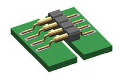
Figure 2: Mill-Max offers a header/jumper solution with Z-bend surface-mount terminations for soldered, daisy-chained connections of two coplanar boards.
Some connector manufacturers also provide spring-loaded options for assemblies that use blind-mating processes as shown in Figure 3. Although this option is typically more expensive, designers don’t need to worry about lining up the connector pins precisely with the socket to make a reliable connection. It is also used to prevent issues around tolerance stack-up during assembly.
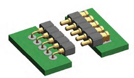
Figure 3: Mill-Max offers horizontal surface-mount connectors in spring-loaded versions for reliable connections.
If the designer needs a more rugged option, and/or has a mixed-technology board, using a thru-hole connector option may be the best choice. Typically, designers opt for thru-hole connectors in these applications to take advantage of the stronger solder connection afforded by the lead mounted through the board hole. This can be advantageous for volume manual assembly processes or blindmating situations where the engagement method can put stress on the connectors and solder joints. Cost can also be another factor. Thru-hole boards can be cheaper than surface-mount boards. Figure 4 shows a thru-hole option with right-angle connections that make it easier to daisy-chain the boards in an LED lighting system.
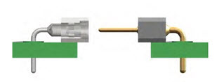
Figure 4: Mill-Max’s thru-hole, right-angle coplanar board-to-board connectors are used to daisy-chain boards in LED strip lighting, offering low profiles and high-temperature insulators for reflow soldering.
Solutions for MR11 and MR16 lead configuration halogen bulbs have been very popular, thanks to their lighting-effect appeal, but have been losing ground to energy-saving LED bulb replacements. These bi-pin LED bulbs, designed to replace traditional halogen lamps generally found in low-voltage applications, require bi-pin receptacles and sockets. Two of the most popular configurations are the MR11 (G4 style) and MR16 (G5.3 style).
Lighting fixture designers should look at the different termination options available when evaluating receptacle and socket solutions. These include thru-hole solder-mount, press-fit, open-bottom, surface-mount, and wire terminations. Also check for pin-to-pin spacing and pin size availability. All of these specs come into play depending on the LED bulb replacement style. This enables the designers to find the right options for their applications, whether the receptacles need to be fixed directly to the circuit board or mounted in housings.
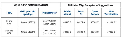
Table 1: Mill-Max recommends a variety of receptacles for G4, GY4, GU4, and GZ4 (MR11) styles. They are available in thru-hole solder-mount, press-fit, open bottom, SMT, and wire termination options.
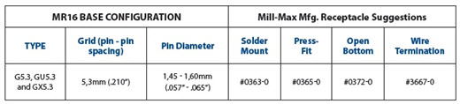
Table 2: Mill-Max receptacle recommendations for G5.3-, GU5.3-, and GX5.3- (MR16) style lamps include thru-hole solder-mount, press-fit, open-bottom, SMT, and wire termination options.
In addition, look for socket manufacturers that can offer quick turnaround for these two-pin sockets based on termination-style requirements. This helps meet production and time-to-market requirements. Manufacturers also should use high-speed, screw machined pins, receptacles, and spring pin components manufactured to precision tolerances to ensure the highest reliability.
In some cases, designers may require a different contact material other than the standard beryllium copper. Check to see if the manufacturer offers additional contact material options such as beryllium nickel, often used in higher temperature applications. Plating options are another consideration. Choose gold for the best corrosion protection and wear resistance; and tin or tin/lead for low-cost, non-critical applications.
Overall, designers need to consider several factors when selecting interconnects for their LED lighting applications, whether LED strip lights or LED replacement bulbs. These include design flexibility, ease of assembly, and feature options in order to meet as many of their design requirements as possible. They also should evaluate these products based on their cost budget, reliability requirements, and available board real estate.
For more information on lighting connectors and the suppliers that manufacture them, visit the Connector Buyers Guide.
Stephen Capitelli is a principal engineer at Mill-Max Mfg. Corp.