Electrical Basics for Microwave Applications
Here is a sneak peek of Bishop & Associates’ upcoming research report on microwave, RF, and millimeter wave connectors.
 Characteristic Impedance
The basic definition of “characteristic” impedance is the value of impedance that causes no change in input when used to terminate a long cable, with “long” being one-tenth or longer than the electrical wave length at the frequency involved. In practical matters, the value of the impedance is not as critical as constancy of the impedance on the system performance. When a cable or PCB interface is terminated with its characteristic impedance, there is no reflected energy and the components are said to be “matched.”
Why 50 Ohms?
Most RF and microwave applications, test equipment, and waveguide transitions have standardized on 50 ± 2 ohms. Connectors for 50 ohms now dominate the microwave and millimeter wave industry. But why 50 ohms? This goes back to development of coaxial cables for KW transmitters in the 1930s. At that time, work focused on air-dielectric cables. Testing showed that insertion loss (for air dielectric) has a minimum of around 77 ohms. The other key concern was “peak power handling,” which for air coax is limited by voltage breakdown (not the same as heating effects, which limit average power handling). The best peak power handling occurs at 30 ohms. The arithmetic mean for 77 and 30 is 53.5 ohms and the geometric mean is 48 ohms. The choice of 50 ohms is a compromise between power handling and signal loss per unit length, but for air dielectric. Since cable length/performance dominates, connectors were developed to match cable specifications.
What About 75-Ohm Cables?
The relatively low-cost cables for video and pulse transmission and long cable runs (CATV) have standardized on 75 ± 3 ohms. These cables normally do not carry power, and they are for commercial applications where cost is important. Often the cable is relatively stiff, with core made of copper-plated steel. The lower the impedance, the larger the diameter of the cable center core. The selection of 75 ohms was a compromise (versus 77 ohms) to help improve cable flexibility.
50-Ohm vs. 75-Ohm Connectors
Physically, the main differences between 50- and 75-ohm connectors can be found in the center pins and dielectric insulators. In some instances, mating 50- and 75-ohm connectors may cause mechanical damage in addition to electrical anomalies.
For example, 75-ohm BNC connectors usually have Teflon as a dielectric and surround the outer spring fingers with air. The center pin maintains a consistent diameter in both the front and rear. 50-ohm BNC connectors, on the other hand, may use Delrin to surround the spring fingers, and the center pin is larger in the crimp area. Different termination crimp tools are needed for each type of center pin. Terminating a traditional 50-ohm BNC connector on a 75-ohm coaxial video cable significantly distorts the digital signal. 50-ohm BNC connectors are used for older analog video applications, but for higher performance A/V applications like HDTVs, 75-ohm BNC devices are necessary.
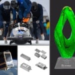
50- and 75-ohm BNC connectors (courtesy of Amphenol)
Connectors most commonly offered with 75-ohm impedance include SMB, SMC, N, BNC (and mini-BNC), MCX, DIN 1.0/2.3, and F.
What Else?
95 ± 5 ohms has been used in limited applications for twinax/dual and triax cables, historically for receiver applications for frequencies under several hundred MHz, direction finding, and antenna systems. Today, 95-ohm is used primarily within the aerospace sector, for video connections in aircraft glass cockpit displays. Connectors with 95-ohm impedance include BNC, SMA, and N.
Fiber optic systems have used 25-ohm cable, and a few 25-ohm SMAs have been produced to terminate this cable. This eliminates the need for a transformer to interface with the rest of the system at 50 ohms.
This is a short excerpt from the upcoming 10-chapter research report from Bishop & Associates entitled, “KHz to THz: RF, Microwave, and Millimeter Wave Connectors,” which will cover in detail history, market, application, product family, manufacturer, and additional information about microwave and RF connectors. For more information, visit Bishop & Associates online.


- IMS2026: New Connectors Enable Higher Frequency Performance - July 14, 2026
- IMS2025 Brings New RF/Microwave Interconnects - July 22, 2025
- New Microwave and RF Advances Impress at IMS2024 - July 16, 2024