Choosing the Right Board-to-Board Connectors for Your Device
Consider robustness, flexibility, and processing requirements in your design to be confident that you are choosing the right board-to-board connectors for your application.
A primary concern for device designers is how to get signal and power to the device in a way that doesn’t interfere with functional goals, such as portability, wearability, or size. Many options are available for connectors that help achieve these objectives. PCB terminal blocks and headers are commonly used connectors for medical device applications. It is important for designers who choose terminal blocks to consider how the PCB is connected inside of the device. In markets such as medical devices, process automation, industrial automation, and building automation, units often contain multiple circuit boards within their end products (Figure 1), which adds complexity to the system architecture.
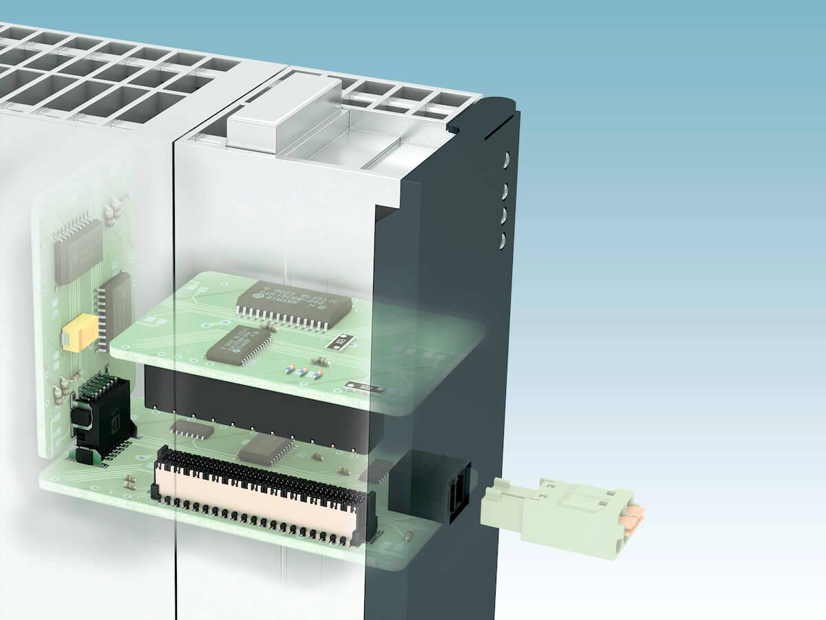
Figure 1: Medical and industrial devices often contain multiple circuit boards.
Within a device, PCBs can be oriented in three positions:
- Mezzanine, meaning they are stacked on top of each other
- Coplanar, where they are connected end-to-end
- Orthogonal, which is also known as a mother-daughter card configuration
Many connectivity products are available in each of these configurations, but for critical applications like interface and I/O modules, controls, communication devices, and patient monitoring devices in medical equipment, PCBs must also meet three requirements: robustness, flexibility, and processing ability.
Robustness
First, let’s look at robustness. Board-to-board products need to be very rugged and robust to endure the operation rigors of industrial and medical use. In high-vibration environments, the contact connection points need to be stable with no intermittencies. One way to achieve this is by increasing the number of connection points on the contact interface. Choosing a product with two individual contact points, or bifurcated contacts, provides an additional measure of confidence for the interface in a high-vibration environment, such as industrial automation (Figure 2).
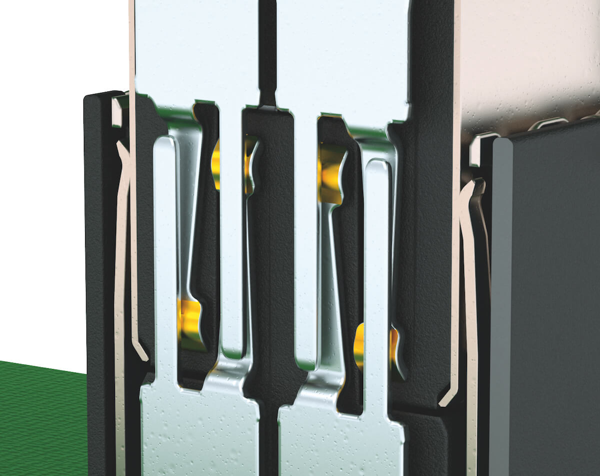
Figure 2: Bifurcated contacts have two individual contact points to provide an additional measure of confidence in high-vibration environments.
Next, a robust mating interface will prevent contact damage if the mating connectors become misaligned (Figure 3). High-tolerance compensation, whether for single or multiple mated pairs on a board, is crucial. Keying of the mating halves and indication of the first pole on the connectors is necessary to prevent mismating of the connector halves. Finally, gold plating on the contact interface allows for a high number of mating and unmating cycles without damaging or degrading the contact interface. Well-designed connectors will support 500 mating cycles, which is considered Level 1 performance by IEC standard 60512-9-1.
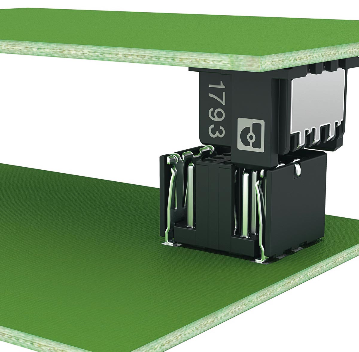
Figure 3: If the mating connectors are misaligned, high-tolerance compensation is crucial.
Flexibility
Flexibility is also important. For medical equipment, building system, and industrial automation applications, designers need flexibility in terms of how they orient the PCBs inside of their enclosures. It is critical that connectors allow for all three PCB configurations: mezzanine, coplanar, and orthogonal (Figure 4).
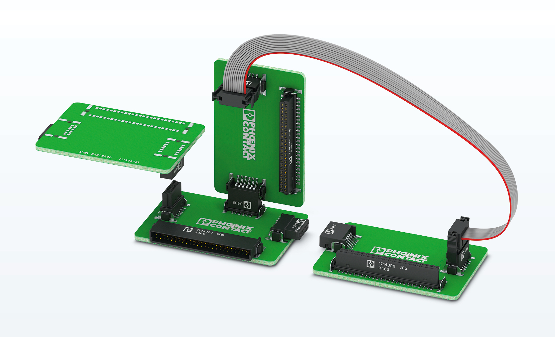
Figure 4: Connectors that allow for all three PCB configurations — mezzanine, coplanar, and orthogonal — will increase the design flexibility.
Additionally, depending on the space constraints of the device, having a choice of different pin sizes and centerline spacings is important. Common centerline spacings, like 1.27mm, are necessary, but smaller centerline spacings, like 0.8mm, are increasingly popular in today’s higher-density PCB designs.
Perhaps of even greater importance is the ability of the board-to-board connectors to have an allowance for the dimensional differences between circuit boards. This is called stack height. Connectors that allow for varying stack heights, as much as 1.5mm, between the boards make the designer’s job much easier, as they do not have to hold as tight a tolerance with their PCB stacking dimensions (Figure 5).
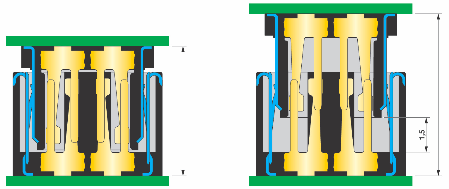
Figure 5: Connectors that allow for varying stack heights do not have to hold very tight tolerances on PCB stacking dimensions.
Another important consideration is the allowable tolerance if there is more than one connector on the board. Due to the tight centerlines, tolerance stack-ups can cause issues with multiple connectors on a board. Fortunately, connector manufacturers can take this into account when designing their connectors, so that even with misalignments up to 0.3mm, the connector can still provide a solid connection to the mating halves. Lastly, given the high data rates board-to-board connectors can handle, shielding is critical for protecting against electromagnetic interference within devices.
Processing Ability
Parts processing and PCB manufacturing are yet another critical consideration. Given the significant advances in PCB designs, the automatic placement of components, such as connectors, onto the PCB is critical. For this reason, high-speed board-to-board products need to be available on tape-and-reel or tray packaging to facilitate automated assembly processes. Further, since most PCBs contain at least some surface-mount components, board-to-board connectors need to withstand the temperature profiles of a high-temperature reflow process. Connector plastics, such as liquid crystal polymers, are ideal for this type of process.
Finally, board-to-board connectors should allow for automatic optical inspection or other inspection techniques. While unshielded parts are easily checked with automatic optical inspection, shielded parts pose a challenge, as their contacts are underneath the part to improve shielding. Computed tomography offers a good solution for these types of products.
By considering robustness, flexibility, and processing in your design, you can be confident that you are choosing the right board-to-board connectors for your application.
Like this article? Check out our board-to-board, terminal blocks and How to Specify articles, our Medical and Industrial Market Pages, and our 2020 and 2019 Article Archives.
- Choosing the Right Board-to-Board Connectors for Your Device - October 27, 2020

