Connector Design and Integration in Crucial Medical Applications
Connector Design and Integration in Crucial Medical Applications
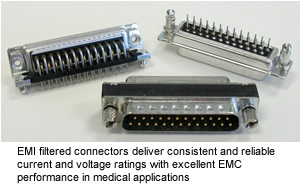
The evolution of critical medical systems and medical imaging equipment has improved patient care. These advanced medical devices have created a new set of design requirements and considerations — sensitive diagnostic equipment used in conjunction with complex monitoring systems entails more detailed planning when designing and specifying connectors. These medical imaging devices require rugged connector configurations that deliver consistent and reliable current and voltage ratings with excellent EMC performance. Material selection is also vital for connectors in medical imaging applications, as magnetic properties must be considered.
Rugged, Robust Sealing
 Depending on where the medical electronic device is used, sealing against intrusion of liquids can be a consideration. Most connectors do not prevent the ingress of liquids into the device enclosure. If the device will be used in areas that could get sprayed or require intensive cleaning, it requires sealing, and an ingress-protected (IP-rated) connector should be specified.
The electrical/electronics industry has broad protection ratings, but most medical electronics in areas that “are likely to get wet” require at least an IP67 rating. This rating ensures that occasional liquid splash or spray from a hose, or even short-term shallow immersion, will not allow liquids to penetrate through an exposed connector and into the device.
The popular D-sub connector is now available from several suppliers in configurations sealed to IP66, 67, or even 68 ratings. Sealing can involve simple potting of the exterior, or the more rigorous internal pottings and use of elastomer seals at the interfaces, or even special molded glass seals. Again, the engineer will have a broad range of product choices, as well as the ever-present cost vs. performance decision.
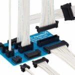
As the primary I/O connector, D-subs are typically used for connecting multiple signals (as many as 78), and in the case of combination D-subs, additional arrangements including power (to 40 amps) and RF signals (to 2GHz).
Other I/O form factors that might require sealing include Ethernet ports (RJ45s) and USB ports (in standard, mini, and micro formats). Sealing may also be needed with a vast array of circular connectors, both industry standard interfaces and supplier-proprietary ones. Manufacturers who require multiple sources should exercise caution in specifying circular connectors. Most of these connectors are available in IP-rated configurations. The choice of a circular connector might also lead to the next consideration, latching.
Latching Systems
Everyone is familiar with D-subs and cables connected with hoods having jackscrews to keep them from unmating. But for devices that require frequent disconnects, alternatives should be considered. In the world of D-subs, there are slide locks and spring latches. Both lend themselves to rapid disconnect and reconnect, even with one hand, in confined spaces. This is an important connector parameter to consider, especially when examining the bigger picture of how the device is used in applications.
Most USBs are friction fit, meaning there is no latch, which can be a problem, but RJ45s have a snap latch. If either of these connectors is configured for IP67, then there are systems using “threaded housings” and quarter-turn bayonet latches. Both prevent accidental disconnect, while still offering a fast, tool-free disconnect when required.
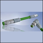
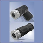
Small circular connectors are also prominent in medical electronics, especially for I/O ports. In addition to the threaded couplings of M8 and M12 type connectors, there are also many proprietary circulars that use a “push-pull” system: Push to snap it on and pull the housing to disengage it. This still offers retention if just the cable is pulled. Price, performance, multiple-source, and size all become intertwined parameters.
Electromagnetic Compatibility and Filter Importance
The use of filters is one of several methods that can help achieve electromagnetic compatibility (EMC). Because EMC is a two-way street, manufacturers have to ensure that their equipment operates as intended, even in “electrically busy” environments, and also must prevent those machines from interfering with surrounding electronics. With the proliferation of electronic equipment in medical areas, this EMC requirement has become more difficult to achieve.
One tool that offers both emission and susceptibility control, while maintaining the signal integrity, is the use of filter connectors. Since they are typically used on the input/output (I/O) connections, filtered D-sub connectors are the most common and affordable filter connector category, and are ideal for many medical I/O ports. In addition to D-subs being a de facto interface on so many equipment types, their use of machined contacts with gold-plated interfaces and all-metal bodies offers high reliability connections, with the added benefit of EMI filtering.
The most common filter component is the capacitor. Capacitors are frequency-dependent; thus, when configured as a shunt-to-ground, they can attenuate high frequencies (which are typically the EMI), while carrying the lower frequency signals — hence, the expression “low pass filter.” Most filter connectors, therefore, typically include one capacitor at each contact position. Attenuations can range from 5 or 10dB to as high as 80dB, depending on the type of filter, the frequency, and the capacitance value. The most popular filter devices typically have a capacitance in the range of 1000 to 2000pF, with an attenuation of 30 to 50dB. Suppliers of filter connectors present the filter performance on a graph (Insertion Loss Curve) showing attenuation vs. frequency.
There are several ways to build a filtered D-sub. Each has its advantages and disadvantages, and there are substantial differences in frequency performance and cost variables. The designer should study the manufacturer’s insertion loss data and consult with their technical support staff to ensure the best selection for the application. Some filter connectors use only inductive components such as ferrites, while others employ more elegant designs that use multiple capacitors plus ferrites. Filter connectors are generally 100% factory-tested, thus maximizing the EMI integrity of the users’ system.
Filter connectors save space (a highly desirable feature in most medical devices), because they typically are the same size as a comparable unfiltered version. They offer better shielding due to the nature of their construction and the materials used; they offer better EMI control than similar looking on-the-board components; and they offer higher-reliability connections, because they typically start with a higher-quality base connector design.
Filter connectors are just one of several tools that EMC engineers use to optimize their products. Other factors related to the connector choice, such as shielding of the interconnecting cables and backshells, must also be considered.
ESD protection can also be added to the connector with chip-style MOVs (metal oxide varistors) placed inside the connector, instead of embedding capacitors or ferrites. Some medical diagnostic tools are designed to sense extremely small currents/voltages, so even a static “zap” could damage the equipment. Designers may add ESD protection to the I/O ports of their devices.
Magnetic Properties
In MRI applications, there are numerous connectors that are close to the high power magnets and sensors used for imaging. Since the presence of magnetic materials can affect the accuracy of the imaging, designers must be careful to assess areas that could benefit from the use of non-magnetic or low-magnetic components, including the connectors. Typical I/O connectors contain steel parts, especially the stamped housings (e.g. D-subs) and mounting hardware. The use of non-magnetic parts (made from brass or zinc, for example) substantially reduces image distortions. Of course, non-metallic housings could be used, too, but that often compromises EMC. As with most engineering decisions, there are always tradeoffs.
Isolation Requirements
Since accessory devices or sensors/probes are likely to come into direct contact with a patient, there are rules and specifications (IEC 60601-1) for isolation against currents that could pass through the patient. This subject is complex, due to the variation of body exposure, applied voltages, resulting currents, and the hazard inherent in the device. Detailed discussion of this specification is beyond the scope of this article. However, in the quest to meet isolation needs, the selection of connectors is likely to involve decisions on conductive vs. insulated housings, creepage, clearances of contacts within the connector, and dielectric withstand specifications which may be far higher than expected, based on the specific circuitry and application.
RoHS & REACH
Materials selection used to be the intellectual property of the manufacturer. With these regulations, detailed reporting needs to be done on the materials used, and most top tier suppliers will provide the data upon request of the manufacturer. Typically, this information is not on the website or the product drawing, since the full material declaration at the homogenous part level (ref. IPC1752) is quite detailed. Since most medical electronics are shipped worldwide, this has become an important documentation stage in the component approval process.
As connector manufacturers consider the stringent regulations of advanced medical application integration, fundamental performance characteristics must be maintained. Non-magnetic, thin-frame, compact connectors must also handle high data speeds without interfering with other data communications. Despite cost targets, all connectors for use in critical systems must still satisfy all existing or potential requirements, posing a unique design proposition for engineers and users alike.
[hr]
By Fred Kozlof, General Manager, ME, CONEC
- Inside Device Connectivity: The Hidden Enabler of Software‑Defined Vehicles - July 14, 2026
- Bringing Modularity to Multi‑Board Systems - June 30, 2026
- Engineering’s Future is AI-Inspired, Human-Led - June 23, 2026