Robust Fiber Optics are Flying High in Satellites and Low-Altitude eVTOL Aircraft
Understanding how different flavors of fiber-optic technologies function in demanding aerospace applications can help designers select the most robust options.
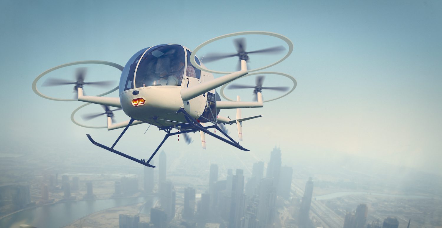
UAM (urban air mobility) and electric vertical take-off and landing (eVTOL) aircraft promise a greener, cleaner alternative to ground transport in cities. Constellations of LEO (low Earth orbit) satellites are launching a new era of data access across the globe. But to make these projects a reality, designers must solve many connectivity challenges in avionics and electronics packaging. Of course, satellites and eVTOL/UAV aircraft electronics operate in very different environments. Looking at the advantages of fiber-optic technologies in both domains helps designers appreciate the robustness of available options, including expanded beam and physical contact fiber-optic interconnects, optical flex circuits, and space-qualified transceivers. By understanding options and collaborating with a qualified manufacturer, designers can achieve an end-to-end solution that succeeds in their specific project.
Why fiber in the first place?
The primary advantages of going with optical fiber are speed, weight, size, and robustness. For speed, fiber optics currently support 100 to 400 Gb/s — more than ten times the speed copper cable supports — with theoretical rates of 200 to 500 trillion bits per second. For weight, fiber-optic glass strand is four times lighter than copper wire of the same diameter. For size, the diameter of a single glass fiber is 125 microns, with cores as small as nine microns with a jacketed diameter under one millimeter. Compare that to ultra-thin Category 6a Ethernet cable where four 200 micron (32 American wire gauge [AWG]) copper wires are contained within a 2.8 mm thick jacket. The result: optic fiber cable is nearly 78% lighter for the same length.
The need for speed differs between satellites and eVTOL aircraft. Individual LEO satellites may transmit up to about 25 Gb/s with total constellation bandwidth measured in multiple terabytes per second. In eVTOL aircraft, CAN bus control-signal data rates operate up to 8 Mb/s; in-flight entertainment (IFE) systems, assuming their use in future six-passenger vehicles, might require around 1 Gb/s.
While the speed requirements differ between the two applications, the desire for weight and space savings is the same. Each extra kilogram in modern LEO satellite missions can potentially add up to $10,000 per launch. In eVTOL aircraft, fuel is not burned off and discharged, but spent batteries literally become dead weight. Each pound and cubic inch saved extends flight time and payload/passenger capacity.
Robustness is also an advantage, but it may seem a surprising one. The installation parameters of optical fiber — including bend-radius and cable-stress requirements — are well known in industrial and commercial applications. In aerospace applications, fiber optics offer three critical contributions:
1) Complete electromagnetic interference (EMI) immunity
Optical fibers are made of dielectric materials that neither emit nor receive EMI, making them an ideal choice for avoiding this common cause of avionics system failure. Cable shielding is not required. Available optical inserts support ceramic ferrules, expanded beam termini, and multimode MT ferrules for PC connectors — all compliant with ARINC, MIL-Spec, and EN standards.
2) Specific to space
Outgassing, the release of gas or vapor by materials in a vacuum environment, is a concern for components used in space applications. NASA has identified space-qualified materials for fiber optic assemblies. The degrading effects of ionizing radiation is another concern that is minimized by employing radiation-hardened fiber with adapted glass compositions.
3) Specific to eVTOL aircraft
System redundancy is required for certification. Fiber optics can serve as a completely independent “fly-by-light” alternative to “fly-by-wire” systems with the bonus of zero EMI.
Different flavors of optical-fiber robustness
The connectors that couple the fiber optic cable to the light source, receiver, and other components come in two types:
- Physical contact (PC) technology physically mates the two ends of optical fibers together.
- Expanded beam (EB) technology uses lenses at fiber end faces to expand and re-focus light within a small air gap in the optical pathway.
PC and EB technology differ in how they handle environmental issues (exposure to water, dust, vibration), termination factors (insertion loss, return loss, misalignment, angularity), maintainability (repair, cleanability, wear), and cable limitations (bend radii, wavelength range).
PC connections for satellite applications
PC interfaces use precision ferrules and alignment mechanisms to minimize optical losses between fiber ends. It’s simply a matter of cleaving, polishing, and joining fiber ends in a butt contact. Ends may be flat polished for digital optical traffic or angle polished for optical sensing applications. It’s a one-and-done process with no need to touch it again — exactly what a mission in space requires. High-quality installation can be performed on the ground, and high optical continuity can be maintained during the vibration, shock, and temperature extremes of spacecraft launch and orbit.
EB connectors for eVTOL aircraft applications
EB interfaces employ a design that expands the light beam across a small gap in the optical pathway. A lens expands and collimates the beam emitted from the launch fiber. The beam remains collimated across the gap until a receiving lens focuses it onto the receiving fiber with an achievable insertion loss below 1.0 dB, just slightly higher than a PC contact. Thanks to the gap, EB interfaces are minimally affected by contamination, misalignment, vibration, and wear.
Multiple connections and disconnections can occur with little measurable insertion loss even after hundreds of mating cycles — exactly what eVTOL maintenance crews require. EB connectors are usually terminated on robust military tactical, and, for eVTOL, avionics/flight-grade cable.
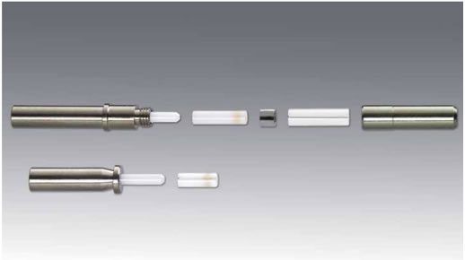
TE Connectivity’s EB16 expanded beam optical pin and socket termini
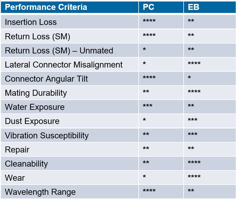
A comparison of physical contact (PC) and expanded beam (EB) fiber optic connector features.
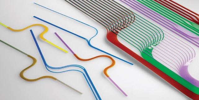
Optical flex fiber moves robustness to a new level
Both satellite and eVTOL applications can utilize relatively new optical flex (OF) technology, which encapsulates individual fibers in a thin, protective film embedded within a rugged, flexible substrate.
In satellites, OF circuits comprised of hundreds, even thousands of individual fibers enable high-density routing of fiber optic channels in backplanes and systems. The circuits can be customized to meet card-to-card and backplane requirements. Crossovers minimize stress while accommodating complex routing arrangements. Added durability and low insertion loss are achieved through controlled optical circuit routing derived from computer numerical control (CNC) machines. OF circuits can manage high fiber counts in small spaces, accommodating up to 12 layers stacked and up to six fiber crossings. Flat OF cable can even be mounted on flat surfaces of a satellite’s payload exteriors.
In eVTOL aircraft applications, OF cable is easily routed in innovative airframe geometries. The flat, robust profile supports tight bend radii and single-mode and multimode applications. Multiple options in cable assembly design, connectorization, and routing can maximize performance in a tailored, form-fitting solution. 3D printing can even be employed to shape interconnects as required.
Enabling a rugged end-to-end fiber-optic solution
In a fiber-optic network, a transceiver converts electrical signals to optical (light) signals and optical signals to electrical signals. It is either plugged into or embedded in another device within a data network that sends and receives signals.
In large commercial aircraft, fiber and copper can coexist in many applications by selecting appropriate media converters, transceivers, and hybrid termini. While rarely relevant in the applications discussed here, it is still helpful to know optical fiber is robust enough to fly at a very high level — for example, meeting the SpaceVPX VITA 66.5 standard for high-density optical MT interface modules. Fiber optic transceivers are available in a parallel optical design capable of achieving 25+ Gb/s while also meeting MIL-Spec standards for robustness.
Today’s advanced optical fiber technologies offer a wide range of robust building blocks that allow designers to find solutions to meet demanding eVTOL aircraft or satellite requirements. Close interaction between systems engineers, network architects, electrical wiring interconnect system (EWIS) designers, and qualified manufacturers early in the design process will often reveal that optical fiber provides surprising advantages.
Visit the Preferred Supplier page for TE Connectivity to learn more about the company and its products.
By Mark Benton and Christophe Prel, TE Connectivity
Subscribe to our weekly e-newsletters, follow us on LinkedIn, Twitter, and Facebook, and check out our eBook archives for more applicable, expert-informed connectivity content.