10 Common Connectivity Challenges in High-Power Electric Aircraft and How to Overcome Them
Design engineers must overcome many connectivity challenges when handling high voltage and high current levels in electric rotorcraft and urban air mobility (UAM) applications.
Electric-powered vertical takeoff and landing (eVTOL) aircraft, rotorcraft, and personal air vehicles (PAVs) employ significant amounts of electrical power to enable vehicle takeoff and maintain flight. As a result, design engineers face many electrical interconnect challenges when handling high voltages and high-kW peak output for electric propulsion motors, inverters, controllers, batteries, infotainment, and sensors. Designers can meet these challenges by understanding how proper product selection and a follow-the-wire design approach can be used to solve 10 common high-power connectivity challenges.
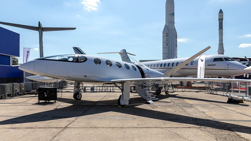
Hundreds of commercial drone and eVTOL programs are driving advances in electric-propulsion motors, distribution, positioning systems, networking, and cockpit/mission systems. These opportunities are inspiring designers to explore SWaP-optimized components, including low-voltage and high-bandwidth interconnect technologies, for line replaceable units in UAM innovations. One such UAM project, the Eviation Alice, is an electric aircraft designed to accommodate nine passengers and two crew. (Image by Matti Blume, Wikimedia Commons, published in accordance with CC BY-SA 4.0)
Electrical challenges for EVTOL Aircraft
1) Preventing partial electrical discharge helps to minimize corona effects, voids, and cavities that can cause insulation breakdown and electrical treeing.
Managing high voltage (HV) in the air is more complicated than on the ground. HV can ionize surrounding air, which then becomes conductive to produce a corona discharge. The corona effect is responsible for electrical power losses through voids, cavities, and electrical treeing. A self-sustaining ionizing discharge can initiate electrical arcing and potentially ignite a fire. Selecting materials with dielectric properties well-suited to HV conditions — such as corona-resistant polytetrafluoroethylene (PTFE) — is one way to effectively minimize risks of corona discharge due to insulation breakdown.
2) Critical voltage stresses require techniques that protect against different voltage
The selection of techniques used to protect conductor parts depends on the characteristics and strength (voltage gradient) of the electrical field around the conductors. Connectors that use conductors with large radii and designs that avoid sharp points and edges help minimize air ionization with relatively low-energy corona effects. To protect against air ionization breaking down dielectric between pins, each pair of conductor pins must maintain an adequate clearance distance as measured through air. These values will change as altitude and temperatures change. Electric discharges can also occur on or close to the insulation surface. A localized, partially conductive path on the insulation surface is called arc tracking. To minimize electric discharges along the insulation’s exterior, each pair of conductive parts — including the binding surface of equipment — must maintain adequate creepage distance as measured on the insulation surface. Creepage distance is typically equal to or larger than clearance distance. Minimum creepage distance can be determined by the insulation’s Comparative Tracking Index (CTI).
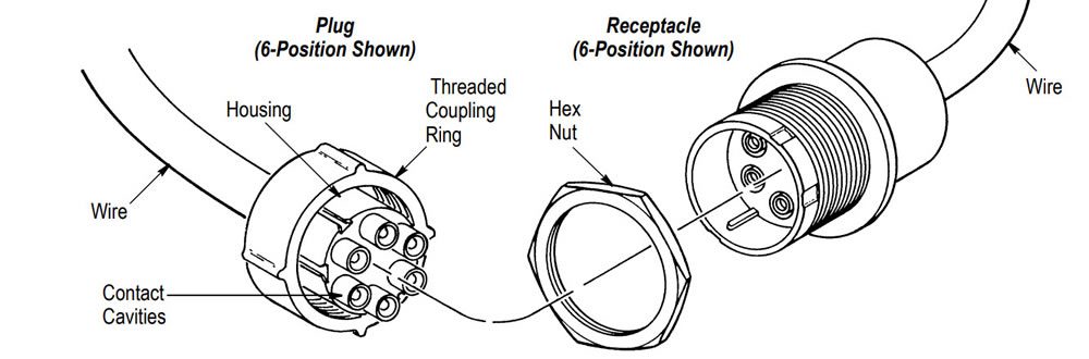
HV connectors protect adjacent pins from arcing by using a male insulation ring that surrounds the female part prior to electrical contact.
3) Avoiding arc tracking damage helps minimize breaches in insulation that can create electrical arcing between wires.
Current on the outer surface of polymeric insulators could create carbon tracks that damage insulation. Carbon tracks can cause the insulator to lose its dielectric properties and instead become an electric transmitter. Electrical arcing can then occur across the conductive path, resulting in power loss with a high probability of ignition. As previously noted, it is critical to maintain a proper creepage distance and use insulation materials that maintain their dielectric properties in HV conditions.
4) Handling high network operating voltages (>3kV DC) requires the selection of relays and contactors that can withstand extreme electrical stress.
Higher network operating voltages impose significant demands on relays and contactors used for propulsion motor power switching, battery charging management, comfort heating for passengers, and other auxiliary functions. HV relays and contactors are available to meet demanding peak load capacity, operating temperature, coil efficiency, short-circuit protection, breaking capacity, and other critical requirements, such as robust shock and vibration performance.
5) Dealing with skin effect helps minimize opposing eddy currents to reduce the effective resistance of conductors at higher frequencies.
When determining proper shielding and filtering for electromagnetic compatibility (EMC), designers must account for skin effect — the tendency of AC to flow close to the surface of a conductor. Skin effect is the result of eddy currents induced by the changing magnetic fields of alternating current and is a factor in nearly every AC design. PCB traces and other elements of AC power circuits can be designed to negate skin effect, but expert planning is required.
6) Managing size and weight constraints in trim aircraft loads calls for the selection of smaller and lighter
Components employed in high-power electrical energy storage and management in industrial applications tend to be hefty. Fortunately for aircraft, high-efficiency relays and contactors are available that can handle higher voltage and amperage within a compact footprint. For example, KILOVAC high-voltage relays and contactors from TE Connectivity (TE) offer voltage ratings up to 70kV DC and current ratings up to 1,000 Amps (A) while providing a useful size-to-power ratio. Compact cables, terminations, and connectors are also available to meet demanding size, weight, and power (SWaP) requirements.
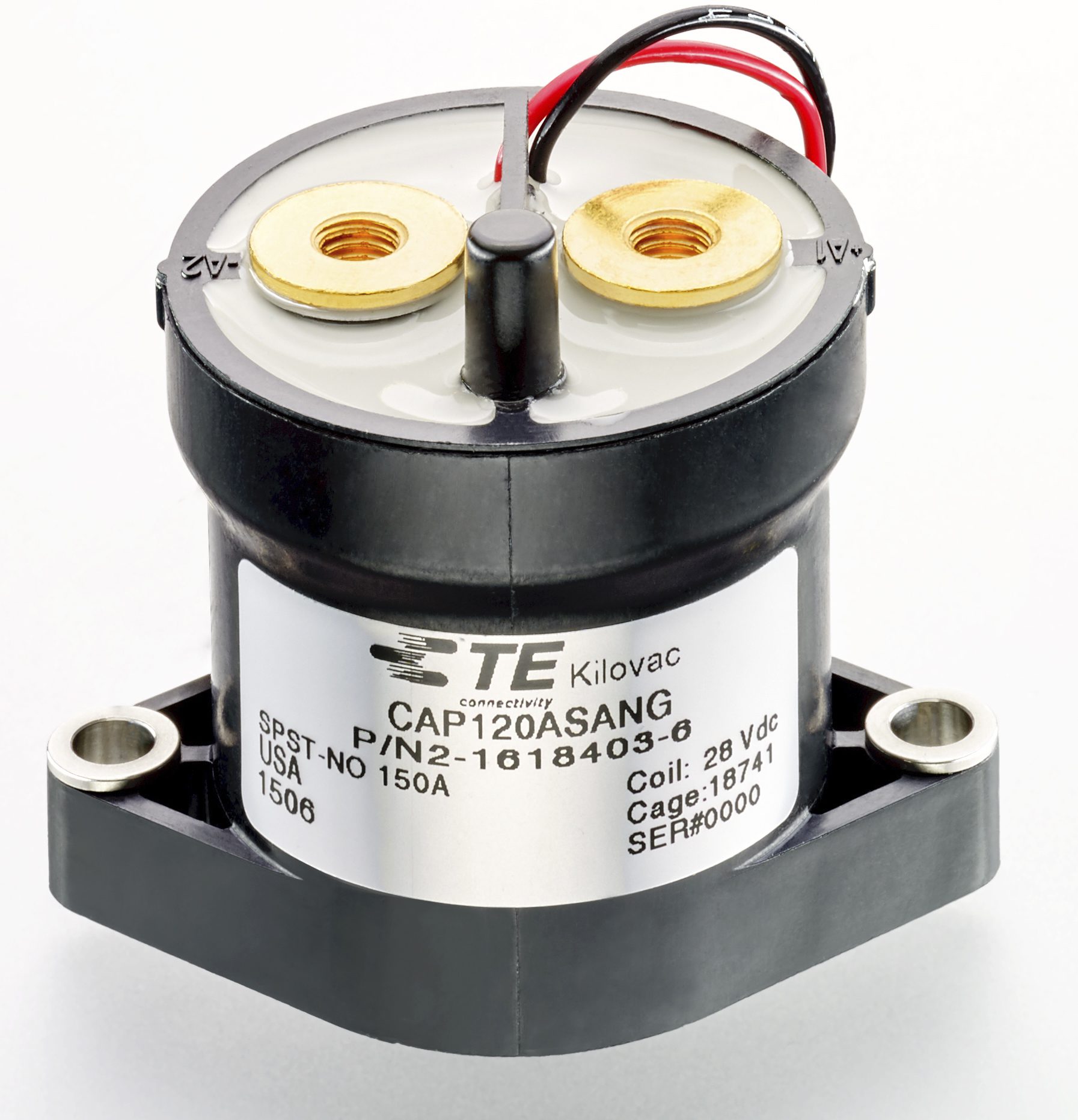
Designed for harsh environments and loads, TE Connectivity’s KILOVAC CAP120 contactor offers exceptional performance for small and light devices. A reduced-size version of the popular MAP and CAP series contactors, the CAP120 contactor’s small size and light weight opens up new application possibilities for 150A/600VDC devices. High break levels — 1,000A at 400VDC and 600A at 600VDC — help increase system flexibility and reliability. CAP120 contactors also provide reliable and long-lasting performance in UAM applications.
Thermal challenges
1) Managing thermal issues requires strategies to dissipate heat in composite structures to create a stable electrical/ electronic environment.
Dissipating heat in composite structures is difficult. Pick-up voltage (VPI) and coil resistance (RC) change as the temperature of wires and relays changes. To ensure electrical stability, designers must determine the steady-state characteristics for the temperature and voltage combination of a DC relay’s operating conditions. The same is true for AC applications, although their VPI varies less with temperature than DC relays. This evaluation ensures proper product selection.
2) Battery charge cycles need to enable higher energy transfer rates by optimizing heat distribution and balance.
High-power charging (HPC) for direct current (DC) presents a challenging electric load profile in eVTOL and UAM applications. Individual components are subjected to temperature extremes at resistance points along the HV path. For HPC system safety, a simulation can apply dynamic load profiles along the complete HV path to identify potential thermal bottlenecks. Every microohm (µΩ) of resistance counts. Areas where resistance should be reduced include cable attachment (termination technology), contact interfaces (crimps and contact types), and contact materials, as well as applying optimized high-voltage contactors and relays. Thermal sensing, thermal system protection, and thermal modeling can also be used to avoid hot spots and design an HV path that can carry short-time dynamic loads.
Power management challenges
1) Handling power management calls for the need to use high frequency switching to enable rapid bus transfer in the event of power loss.
Variable-frequency AC power is used for typical aircraft loads. But fixed frequency 400Hz AC power enables smaller and lighter transformers and motors, as well as faster transfer of bus power if power is lost, all of which is ideal for eVTOL applications. Hermetically sealed enclosures provide protection in severe environments. Modular power distribution units or backplane-type panels can be customized for fixed-wing aircraft and rotorcraft applications.
2) Hybrid electromechanical and solid-state power switching technologies call for the need to evaluate the advantages and disadvantages of both.
Solid-state relays (SSRs) offer silent operation, low electrical interference, functionality over a wide range of input voltages, low power consumption, and no electrical arcing. Additionally, zero-voltage crossover minimizes surge currents. SSRs are essentially electronic circuits; they employ no moving parts and resist the effects of physical hazards including shock, vibration, and changes in altitude. But as with any electronic circuit, SSRs are sensitive to ambient heat and require a heat sink. They are also vulnerable to power surges.
Electromechanical relays (EMRs) are far more tolerant of surges and overloads and can switch any AC or DC load up to their maximum rating. EMRs will operate at full load over a wide temperature range without requiring a heat sink.
However, EMRs arc when contacts open and close, which can affect nearby equipment sensitive to radio frequency interference (RFI). Consequently, EMRs are suitable in applications with heavy surge currents or spike voltages that tolerate RFI. Relay manufacturers should be consulted for SSR and EMR selections that fit particular applications.
Follow the wire to meet high-power challenges
To uncover hidden factors compromising power and signal reliability, designers can employ a follow-the-wire methodology. Success depends on viewing interconnects holistically, as part of the system, rather than as an afterthought. In other words, every connection counts. Industry standards groups also provide insights to solve technology problems at the sub-system and component level.

A wide range of TE Connectivity products address the unique needs of UAM and eVTOL projects.
Solution providers with extensive expertise in high-power applications and a broad product portfolio can help designers strike the right balance between performance, cost, and time to market. Designers who need to rapidly iterate prototypes and products benefit by working with a manufacturer who can design, customize, manufacture, and implement all the components along the wire. A connectivity partner with broad experience can also offer innovative solutions that help eVTOL and UAM projects soar over roadblocks.
Visit the Preferred Supplier page for TE Connectivity to learn more about the company and its products.
Like this article? Check out our other Harsh Environment and Commercial Aviation articles, our Transportation Market Page, and our 2022 and 2023 Article Archive.
Subscribe to our weekly e-newsletters, follow us on LinkedIn, Twitter, and Facebook, and check out our eBook archives for more applicable, expert-informed connectivity content.