Is Boosting the Current the Solution to Faster EV Charging?
Rated boost current, in which short-term currents exceed the rated continuous current, reduces EV charging times. New innovations in contact technology make it a viable solution.
By Joydip Sanyal, a Chartered Mechanical Engineer, Smiths Interconnect
Expanding and updating the EV charging infrastructure to deliver ultrafast CCS (combined charging system), particularly along highways and in major cities, is pivotal for the continued adoption of battery electric vehicles. In many countries, the automotive industry is preparing for generational change in how we fuel our vehicles, and various innovative solutions are being introduced to improve charging technology. One effective strategy is the use of rated boost current, which involves short-term currents exceeding the rated continuous current[1]. The boost current mode reduces charging times, a goal the industry has been working towards to bring parity to the EV charging experience, making it as fast to refuel an electric vehicle as an internal combustion engine vehicle.
However, one common weakness creates a challenge for ultrafast CCS technology: power loss, which happens due to Joule heating of DC+ and DC- sockets. While power loss may seem innocuous, given its prevalence in the industry, if it is not addressed, it can be a major barrier to the adoption of electric vehicles. A solution exists. Chargers with rated boost current technology provide a fast EV charging experience, a win-win situation for drivers as well as CPOs (charge point operators).
A connector solution
The contact technology used for DC+ and DC- sockets within the CCS plugs for ultrafast charging are machined. While a vehicle is charging, the contacts within the plug make contact with machined pins in the EV’s socket or charging port. The surface finishes of these contacts are not smooth; they are comprised of many asperities, or areas of microscopic irregular surface areas. These areas on the material’s surface, also called a-spots, provide the only conducting paths for the transfer of electric current. They are smaller than the full length of the contacts (see Figure 1).
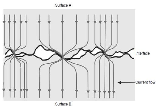
Figure 1 – Electrical constriction resistance
Since the conducting paths are constricted through the a-spots, the electrical resistance increases. This increase is called constriction resistance. Further, contaminant films on the mating surfaces increase the resistance of a-spots. The total resistance due to constriction and contaminant films is known as contact resistance. The constriction current produces Joule heating and increases local temperature, which further exacerbates with thousands of mating cycles. The higher the electrical contact resistance, the higher the level of contact overheating and unwanted power loss.
Case Study: A contact solution
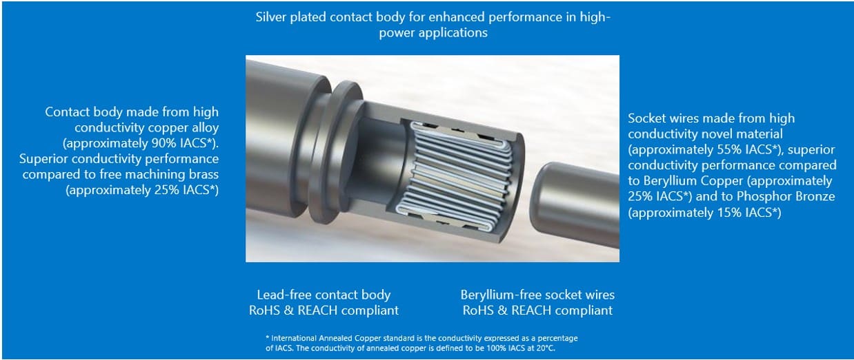
Interconnect suppliers have experimented with various design strategies to mitigate these challenges. One solution, Smiths Interconnect’s Hypertac Green Connect socket, designed to IEC2196 and SAE J1772 standards, can deliver up to 90% more energy at 500A boost current mode. This represents a significant improvement over existing technologies, allowing faster, more efficient charging with less energy loss.
Designed for ultrafast high-power charging, the Hypertac Green Connect excels in boost current mode, providing longer periods where current exceeds the rated continuous current. The contact is built to endure up to 60,000 mating cycles — a lifespan far exceeding most alternatives in the market — ensuring that CPOs can rely on the same connector for extended periods without incurring additional service cost and performance degradation.
The lead-free and beryllium-free hyperboloid contact is set in a body made from high conductivity copper alloy (approximately 90% IACS or International Annealed Copper Standard) to deliver superior conductivity performance compared to other CCS DC+ and DC- sockets, which are manufactured with brass (approximately 25% IACS). Further, unlike other socket technologies which are stamped to a hyperboloid geometry with high electrical contact resistance, the Hypertac Green Connect socket has wires in the hyperboloid cage made from high conductivity novel material (approximately 55% IACS).
Testing a new connector solution
To ensure performance, designers exposed the Hypertac Green Connect to a series of intense performance, safety, and exposure tests.
Mating cycle test – A test bench was set up, where the pin and socket pairs were mated and unmated up to 60,000 cycles, keeping all other variables the same. At the end of 100, 500, 1000, 2000, 5000, 10,000, 15,000, 20,000, and then increments of 10,000 cycles, the machine was stopped to carry out certain critical measurements on contact resistance, temperature rise, and energy transmitted at 500A.
Contact resistance test – The test setup involved applying 100 Amps through the contacts and then measuring the voltage drop across the pin and sockets. The objective of this test was to observe the behavior of the contact resistance across the product’s lifecycle (up to 60,000 cycles).
Temperature rise test – In this test, 1.5 m of 70 sq mm cable was terminated on each of the contacts, and 250A was applied through each of them. This current was applied until the samples under tests reached thermal stability. Temperature rise was then measured through the difference between the temperature reached by the contacts and the ambient temperature. The objective of this test was to observe the temperature rise and whether it exceeded the critical temperature required for derating.
Ability to keep low contact resistance and low temperature is possible through a high number of contact points with the wires of the hyperboloid cage and the high conductivity of the new wire material. In addition, the development of an additional feature within crimp termination allowed further reductions in the heat generated in the connection between the cable and the socket. The results demonstrate, Hypertac Green Connect can carry more current without the need to increase the size of cable.
Boost current mode test – In this test, 500A of boost current was applied to the samples under test through 1.5 m of 70 sq mm cable and time was measured for +50 °C temperature rise. The objective of this test was to understand how long (boost duration) and therefore how much energy (kWh) could be transmitted within the +50 °C temperature rise.
After conducting all the tests, the results confirm that the Hypertac Green Connect can deliver superior mechanical durability, electrical performance, and longer boost duration. In the demonstration, the plating experienced little wear with no exposure of the base copper alloy even after 60,000 cycles. Low contact and temperature rise, resulting in extended duration for boost current ultimately delivered up to 90% more energy at 500A boost current mode. The technology delivers significant improvement over conventional connector technologies, allowing reduction in charging time, more efficient charging with less energy loss, and shorter cooling down duration, all of which collectively will help CPOs with higher revenue and greater intervals for replacing contacts.
Joydip Sanyal, a Chartered Mechanical Engineer, has 18 years of experience in the industrial automation, industrial IoT, and electromechanical components industry.
Visit Smiths Interconnect to see more connectivity solutions.
[1] Holm, R., Electrical Contacts, Springer
Like this article? Check out our other articles on High-Speed and EV’s and HEV’s, our Automotive Market Page, and 2025 Article Archives.
Subscribe to our weekly e-newsletters, follow us on LinkedIn, Twitter, and Facebook, and check out our eBook archives for more applicable, expert-informed connectivity content.
- Is Boosting the Current the Solution to Faster EV Charging? - July 22, 2025