Innovative Interconnect Solutions to Common Signal Integrity Challenges in High-Frequency, Compact Systems
Insertion loss, return loss, crosstalk, and noise floor challenge engineers in high- speed systems. New strategies help mitigate these factors and preserve signal integrity.

In today’s high-speed electronic systems, achieving optimal system performance requires high levels of signal integrity. However, there are several limiting factors, including insertion loss, return loss, crosstalk, and noise floor. At the same time, the smaller compact systems call for higher-density, lower-profile interconnect solutions.
Insertion Loss
In a high-frequency coaxial cable medium, insertion loss can be seen as the power absorbed or lost in a transmission line or RF cable as a result of the insertion of a connector/interconnect. Attenuation of a signal is directly proportional to the length of the cable. At frequencies around 16 GHz, the insertion loss in both stripline and CPW-type copper traces in a printed circuit board becomes significant to the extent that the transmission of a high-frequency signal from one device on board to the other is a challenge. Even slight impedance discontinuities and mismatches result in high signal loss and reflections on the channel make signal sampling quite difficult. Preserving signal integrity is a key challenge.
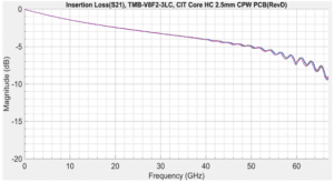
Figure 1 shows the insertion loss of a signal in the range of DC to 65 Ghz traveling on a 1” long Cu trace on a five-layer, 4.11mm-thick Tachyon 100G test board. There is about 10dB max insertion loss at 65 GHz signal in 1” of board trace, which results in significant signal loss.
To mitigate this insertion loss, the interconnect solution needs to have well-shielded, low-loss coaxial cables whose impedance is well matched to the impedance of precision connectors used both on cable and board sides.
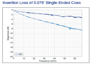
Figure 2 compares the insertion loss of the same signal when traveling over CarlisleIT’s new CoreHC interconnect using 0.079” coaxial cable and compression-mount board-side interface. Insertion loss data shown in dark blue shows the trace measured and de-embedded for a 1’ (~ 28 cm) long, 0.079” wide coaxial cable in the CoreHC interconnect assembly. And the trace in sky blue shows the insertion loss of the same signal when traveling through a 28 cm long CoreHC channel and 1” of Cu trace on low-loss Magtron board. The overall insertion loss of 10dB through cable and board medium is minimized to just ~ 3.1dB, when the same signal of 65 GHz travels on the CoreHC channel only excluding the Cu trace.
Return Loss
Return loss is another important factor at higher frequencies. Return loss is the difference in the amplitude of incident and reflected waves traveling on a cable. It is measured on a negative scale. Higher return loss means a better impedance match between the source and load.
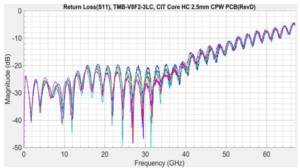
Figure 3 shows the return loss of a signal in the range of DC to 65 GHz when traveling over 1” Cu trace of Tachyon 100G PCB. The signal falls apart at frequencies higher than 40GHz, mainly due to higher reflections resulting from impedance mismatch between load and source (Rx and Tx ports).
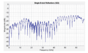
Figure 4 shows the return loss for the same DC – 65 GHz signal when traveling on a 1’ long 0.079’’ CoreHC interconnect channel. The signal is good and can be sampled up to 65 Ghz. Insertion loss stays less than -15dB even at the highest frequencies (from 40 GHz to 60 Ghz).
Eye test is another important criterion in sampling high-speed, high-frequency digital signals traveling on PCB trace and in coaxial mediums. Rise and fall times, eye amplitude, eye width and height, and jitter are key parameters in time domain eye test using BERT Scopes. A well-open eye pattern means all these parameters are within the specified limits of the test mask needed for error-free sampling on the receiver side. The closing of the eye means there is an increase in rise and fall times, reduction in eye amplitude and height, and increase in eye width, which can affect the signal sampling and result in high bit error rates on the receiver side.
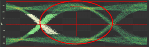
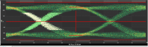
Figure 5 shows the eye pattern for 1’ long 0.079” coaxial cables used in the Core HC interconnect, and Figure 6 shows the same eye pattern for 1’ long 0.079-inch coaxial cables and 1” of Cu trace introduced in the signal path along with the coax cables. 25 Gb/s data is transmitted using PRBS7 pattern, and the pattern length is 511 bits. Notice the slight closing of eye when PCB trace is added in the test path of CoreHC coaxial cables. Since this closing of the eye is almost negligible and does not affect the sampling of high-speed signals, CoreHC Interconnect can be used effectively to jump high-speed signals over Cu traces in high-density boards.
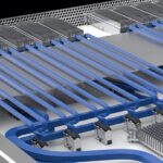
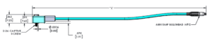
Another challenge is to get as close to the IC pins as possible and keep the trace on the board short so that the high-frequency signal can be tapped with minimal loss. Most of the time, the limited clearance on the board restricts the placement of the interposer next to the device under test (DUT). A tighter channel-to-channel pitch of 2.5mm in CoreHC helps to achieve an overall smaller size of just 32.2 mm x 12.5 mm for an eight-channel solution, allowing the interconnect to sit right next to the DUT on the PCB, as shown in Figure 7.
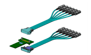
Limited vertical clearance of a system can prevent the use of interconnects with board-side connectors or interposers. As shown in Figure 8, with the profile height of only 9.20 mm and a compression-mount board-side interface, the CoreHC interconnect is mounted directly on the footprint of the PCB, eliminating any need for a board-side connector or interposer. Its low-profile height makes CoreHC an excellent choice in small compact test systems, where vertical clearance can be limited. It also offers a high-density and compact size with multiple channels and a channel-to-channel pitch of just 2.5 mm.
Crosstalk and Noise Floor
Crosstalk and high noise floor affect the signal quality in RF sub-systems. Shielding effectiveness is the ability of the cable assembly to either reject interference from the surrounding environment or prevent the signal in the cable assembly from leaking into the surrounding environment and causing interference to other nearby systems or sub-systems. With two silver-plated copper layers, a PTFE interlayer between the two layers, and outer extruded FEP jacket, the coaxial cables of CoreHC interconnect offer shield effectiveness of about -130dBm at 1 GHz and very low crosstalk performance of less than -40dB over the complete frequency range of DC to 65 GHz. The high shielding effectiveness and low crosstalk results in high signal fidelity, which is needed in today’s compact radio systems, including GSM and 5G transmitters and receiver antennas.
Carlisle Interconnect Technologies’ right-angle CoreHC interconnect solution is available in 2, 4, 6, and 8 channels and supports signals from DC to 65 GHz. It can be used with both coplanar waveguide (CPW) and stripline PCB traces. Depending on the loss budget and flexibility needed, either 0.047’’ or 0.079’’ coax cables can be selected with standard two ps or less inter-pair phase matching.
Visit Carlisle Interconnect Technologies online to learn more about end-to-end Test & Measurement cable and interconnect solutions.
Like this article? Check out our other Wire & Cable and New Technology articles, our Datacom/Telecom Industry articles, and 2022 Article Archives.
Subscribe to our weekly e-newsletters, follow us on LinkedIn, Twitter, and Facebook, and check out our eBook archives for more applicable, expert-informed connectivity content.