Connector Contact Materials for Elevated-Temperature Applications
Applications that reach high temperatures require rugged connectors that can withstand these harsh operating environments. A variety of spring and contact materials should be considered.
The consumer electronics market segment dominates product manufacture. Consequently, vast sums of design, packaging, and reliability criteria are focused on meeting consumer market buying patterns at the lowest possible cost. One metric that is evaluated is operating temperature. The upper temperature limit for consumer products may reach 100°C (212°F), which is a very manageable temperature from a connector performance and cost perspective.
Other electronic market segments do not enjoy the volume leverage of the consumer segment, and many of these segments have far more challenging temperature exposure ranges. Standard off-the-shelf connectors may fail in these demanding applications, so rugged components designed for those markets are often the correct choice. Characterizing applications in terms of temperature exposure can help specifying engineers identify connector contact materials especially designed to withstand elevated-temperature environments.

The automotive electronics market segment includes many applications that are exposed to high-temperatures that standard off-the-shelf connector products are not designed to withstand.
Elevated-Temperature Environments
Several electronic market segments and anticipated temperature exposure ranges are summarized in Table I. With the exception of the military and aerospace market, the upper temperature limits for the other segments significantly exceed consumer limits (100°C).
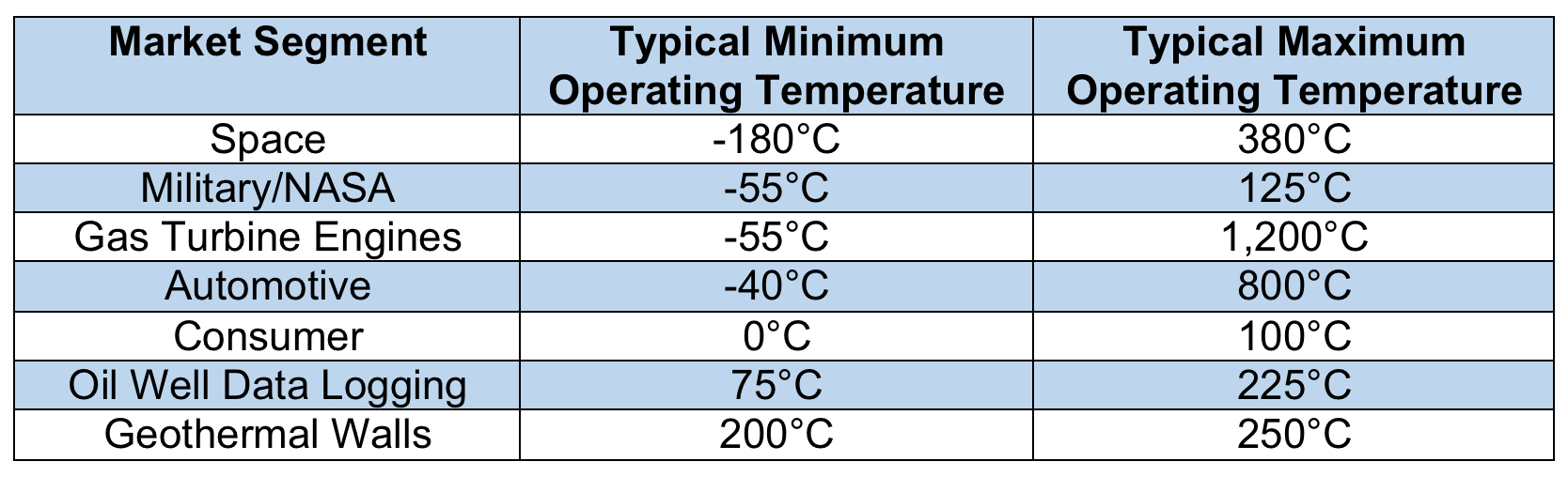
Table I: Typical operating temperatures for several electronic market segments.
The Arrhenius equation is a formula for the temperature dependence of reaction rates:
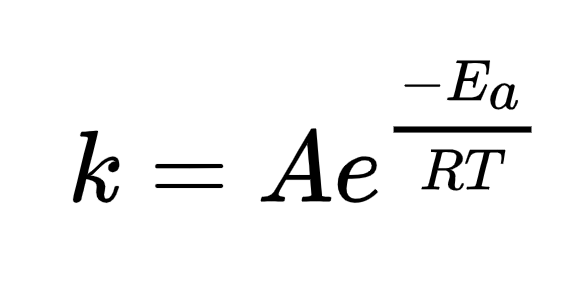
In this formula, k is the rate constant, T is the absolute temperature in kelvin, A is the pre-exponential factor (a constant for each chemical reaction), Ea is the activation energy for the reaction (in the same units as R*T), and R is the universal gas constant, to determine the temperature dependence of reaction rates. For Arrhenius-type reaction behavior, it can be estimated that the reaction rate doubles for each 10° increase in temperature. Therefore, a 25° increase would increase the rate by a factor of 6 (22.5) and a 125° increase would increase the reaction rate by a factor of 6,000. By this logic, it is safe to assume that components that barely function at the upper temperature limits of consumer applications would rapidly degrade in more demanding environments.
Table II details the temperature profile for the automotive market segment. The anticipated underhood temperatures of 150°C or 200°C have not been realized using standard designs and wiring technology. Maximum peak temperatures of 125°C have been recorded, albeit with considerably lower steady-state temperatures, and newer designs and wiring technology will significantly increase these peak temperatures. Mechatronics is the placement of electronic controls directly on an electromechanical device (e.g., on-engine, on-transmission, wheel-based, and exhaust stream). These various devices are interconnected via a common bus. While engine and transmission controls will experience anticipated peak temperatures, wheel and brake controls will exceed these limits by 50°C to 100°C.
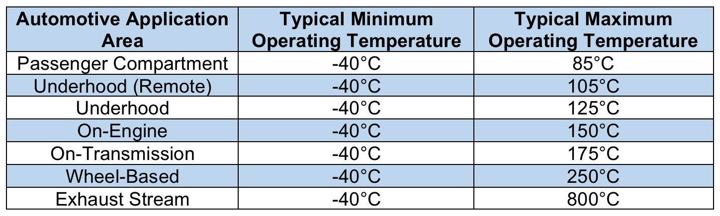
Table II: Temperature profiles for various applications within the automotive market segment.
Thermal effects are cumulative, so the net effect of several short-term exposures is equal to a single exposure for the equivalent amount of time. In order to design and qualify parts for elevated-temperature applications, the thermal profile must be understood. It is important to know, for instance, whether the exposure will be more or less isothermal, as is the case for geothermal walls, or whether there will be a distribution of temperatures akin to automotive demands. Knowledge of the thermal distribution will lead to a reliable test plan.
Connector Failure Modes and Effects
There are two failure modes associated with thermal exposure. The first is a loss of normal contact force, which can result from thermal expansion effects between the spring material and the plastic housing, reduced strength in the spring material at temperature, and stress relaxation of the spring material. The second failure mode is insulating film formation on the contact material surface, which typically results in a complete barrier to conduction across the separable interface. Films may form due to the outgassing of plastic housings or other adjacent volatile materials, or via the diffusion and subsequent oxidation of non-noble metals on the contact surface. The common effect is an unacceptable rise in contact resistance. Reductions in contact force lead to reductions in the real area of contact and, as such, a rise in contact resistance. Mechanical stability is also affected by such reductions and may lead to intermittent interruptions.
Connector Spring Materials
The majority of connector spring materials are copper-based due to the inherent conductivity of copper. Strength levels are achieved by work hardening: a combination of solid solution and work hardening or precipitation hardening. The strengthening mechanism and the degree of alloying determine the upper temperature application limit. High copper alloys with less than 5% alloying content tend to rapidly lose strength at elevated temperatures. For example, pure copper (Cu) will fully anneal in as little as 15 seconds at 315°C. During short-term exposures, C51000 phosphor bronze starts to demonstrate reduced normal force at 100°C, while more highly alloyed materials, such as C72500 (Cu-Ni-Sn), demonstrate only a moderate reduction at 200°C. Both materials are sensitive to stress relaxation during long-term exposure.
Precipitation-hardened copper alloys such as C17200 (beryllium copper or Alloy 25), C17410 (mill-hardened beryllium copper or Alloy 174), C7025 (Cu-Ni-Si-Mg), C7026 (Cu-Ni-Si), andC72900 (Cu-Zn-Sn-Fe-Pb-Mg-Mn-Ni-Nb) retain normal force at elevated temperatures and also demonstrate resistance to stress relaxation during long-term exposure to 200°C. However, both oxidation and strength reductions are concerns for temperatures above 200°C. Non-copper materials, such as stainless steel, are noted for their high strength and oxidation resistance and should be considered for spring material designs operating above 200°C.
Connector Contact Materials
Commonly used connector contact materials are applied to the spring material by electroplating or inlay cladding processes. In general, electroplated materials are limited to lower operating temperatures than clad metal inlays due to the inherent microstructure of the two materials. Electroplated materials tend to have extremely fine grains when compared to clad contact materials, and fine-grained materials have more grain boundary area and are therefore prone to grain boundary diffusion at elevated temperatures. The structure of cobalt- or nickel-hardened gold (Co-Au or Ni-Au) is a complex of gold grains surrounded by an organometallic material within the grain boundaries. These grain boundaries are much wider when compared to those in unhardened deposits. In fact, diffusion rates along grain boundaries in hard gold (i.e., gold with a Knoop hardness of 120–300 and a purity of 99.7–99.9%) approach those measured on free surfaces limiting the use of hard gold to temperatures below 125°C.
Connector contacts are electroplated or inlay clad with various materials to achieve application-specific performance characteristics, including robust resistance to high-temperature operation over long periods of time.
The two exceptions to the clad inlay dominant rule are tin (Sn) and pure or soft gold (i.e., gold with a Knoop hardness of 60–85). The upper temperature limits for tin are independent of application method, as the failure of tin connectors exposed to elevated temperatures is caused by the consumption of the tin via a chemical reaction with the copper in the spring material that forms an intermetallic compound. The absence of free tin on contact surface precludes metal-to-metal contact across the interface. It is also worth noting that tin on stainless steel has been evaluated at temperatures up to the melting point of tin with no significant degradation in contact resistance because tin does not form intermetallic compounds with stainless steel. Above 175°C, however, electroplated pure gold and soft gold will fully anneal as well, which coarsens the grain structure, decreases the grain boundary area, and reduces sensitivity to diffusion effects.
Diffusion Studies
Several comprehensive diffusion studies have been undertaken to understand the behavior of contact materials at elevated temperatures. Below 250°C, defect-assisted or grain boundary diffusion dominates. Concentration profiles generated after exposure to elevated temperatures depict high concentrations at both the contact surface and the original interface and smaller amounts of material within the contact material.
Above 175°C, the nickel diffusion barrier becomes the source for non-noble contaminants at the surface. If a nickel barrier is specified, then the contact material thickness must be increased to form a physical barrier to nickel diffusion. Both electroplated palladium (Pd) and clad inlay (60Pd40Ag) are effective barriers to nickel diffusion. These materials have been successfully applied between nickel and the contact material to extend the upper temperature limit.
Design Guidelines
Table Ill contains recommended upper temperature limits and contact material thicknesses for a variety of connector contact materials. This data was generated by evaluating contact resistance changes before and after isothermal aging for 3,000 hours at temperature.
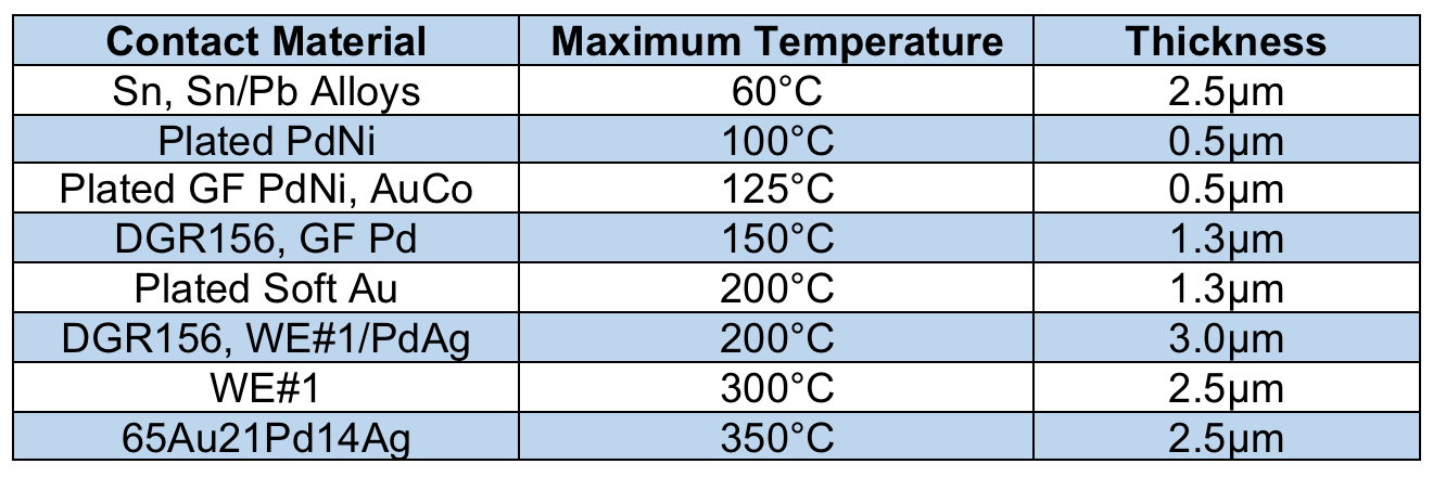
Table III: General guidelines for contact material selection and thickness based on maximum operating temperature.
For application-specific assistance with connector contact materials designed to withstand elevated temperatures and myriad other challenging operating conditions, contact the expert chemists and engineers at your preferred advanced materials supplier.
Like this article? Check out our other Materials, Connection Basics, and Harsh Environment articles, our Automotive and Transportation Market Pages, and our 2020 and 2019 Article Archives.
- Combating Corrosion in High-Reliability Connectors - October 20, 2020
- Connector Contact Materials for Elevated-Temperature Applications - July 28, 2020