Choosing the Right PCB Mounting Method for High Shock and Vibration
Electronics that are subject to harsh military and aerospace operating environments require secure mounting. Several popular specifications give designers options.
A few weeks ago, I was discussing work with an engineer friend, and we got onto the subject of connectors that are subjected to high shock and vibration loads. Exciting, I know. It all stemmed from some questions around some test failures his team was seeing during the vibration portion of the testing process. Curious, I asked what connector type is being used, and the conversation moved to through-hole versus surface-mount, which feels like a great topic to address in more depth with a larger community of design-minded people. Here we’ll take a closer look at through-hole and surface-mount connectors and examine some of the differences between the two types. Each application is different, and there are a multitude of reasons to choose one connector solution over another.
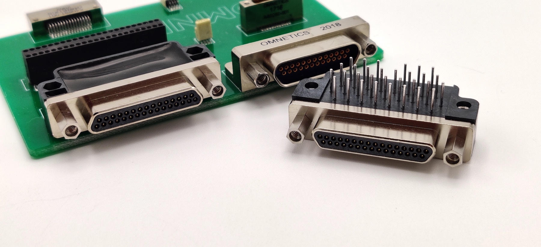
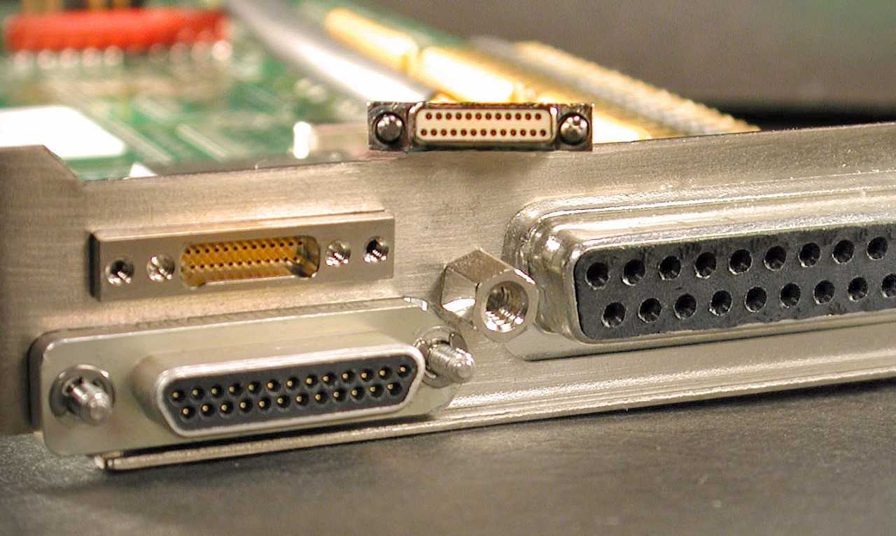
D-sub, Micro-D, and Nano-D Connectors
To narrow the field slightly, we’ll look at connectors from the popular 24308, 83513, and 32139 specifications, which are D-sub, Micro-D, and Nano-D, respectively. The 24308 and 83513 have been around since at least the early 1980s. The 32139, on the other hand, is more recent; it became a standard in 2003. Generally speaking, these specification numbers are for through-hole solutions; surface-mount connectors aren’t covered by these specifications. But your preferred connector company typically has a surface-mount solution that will serve the application requirements.
Back in the late 1960s, and even into the ’80s, wave soldering was a very common method of attaching components to the board. In this method, the wires stick out underneath the board and are partially submerged in liquid metal or solder. That solder then wicks up the leads to fill gaps between the lead and through hole. It transitions out of the wave and the solder cools and solidifies, thereby holding the components onto the board. Both 24308 and 83513 connectors can be attached using this method.
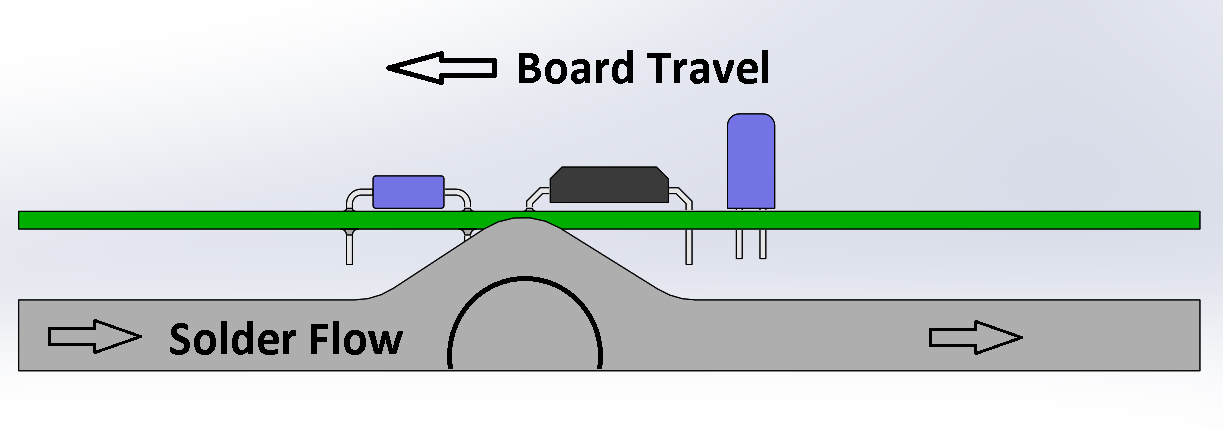
In wave soldering, the solder flows under the connector, capturing the wires in the liquid solder to attach it to the PCB. When the solder hardens, the connector is securely mounted.
People were doing some surface-mount processing during this period, but it wasn’t as common. However, equipment manufacturers were working on new solutions, and surface-mount technology really started to become available in the ’80s. By the late ’90s, it was easier to find surface-mount technology due to the fact that contract manufacturers had started focusing on that technology as designers moved away from through-hole mounting and wave soldering.
Today, designers are able to choose from a very different selection of attachment methods. Processing technologies, such as wave solder, now have alternate methods, such as selective soldering, pin in paste, or even hand assembly for less common parts. So why would we still use through-hole parts? Let’s take a look at the connectors themselves.
D-sub connectors, or 24308s, became an official spec in the early 1980s. The contacts are spaced 0.1″ apart, the PCB leads can be from 0.020″ to 0.040″, and they carry from 3A to 7.5A, depending on the application. For comparison, a board-mount-style connector with 15 contacts can be in the neighborhood of 8.50 grams. For shock and vibration purposes, they are tested to 50g and 20gwhile monitoring for discontinuities.
Micro-D connectors, per 83513, have a smaller footprint at 0.050” spacing between contacts. Leads are 0.020″ in diameter to carry a max of 3A. A through-hole connector with 15 contacts can be in the neighborhood of 3.5 grams and also meet the same 50g and 20g shock and vibration requirements. Similarly, a surface-mount connector that meets these same current, shock, and vibration requirements with the same number of contacts can also be found around 3.5 grams.
Nano-D connectors, per 32139, are the smallest of the group. These contacts are spaced 0.025″ apart and carry 1A through a 0.010″ diameter lead in normal operation. A through-hole connector with 15 contacts can be in the neighborhood of 0.65 grams and, like the others, meet the 50g and 20g shock and vibration testing requirements. For comparison, a 15-position surface-mount is 0.45 grams.
Secure attachments help mitigate potential vibration and disruption to the connection.
The term SWaP refers to size, weight, and power. To perform well in environments where shock and vibration is an issue, designers should try to use the smallest, lightest-weight connector they can to reduce the mechanical stress introduced to the board during operation. Connector mounting styles and support structures can be a critical part of making these solutions successful. Designers and manufacturers can employ a number of mounting techniques, like staking, under-filling, potting, or even special brackets or covers to add additional security and shielding.
When your application experiences higher shock and vibration loads, it’s time to contact your favorite connector company to explore options for connectors that can endure the operating environment. Materials can vary to allow for weight, temperature range, resistance, conductivity, or appearance. Additionally, it’s not uncommon to find situations where custom or hybrid-style connectors are needed, such as applications that require a small package size with nano size signal contacts and several micro contacts to carry power.
Keep in mind, the overall component weight and how it’s going to be supported on or through the board is a critical part of choosing a connector that will pass standard shock and vibration tests.
These are just a few considerations that may come up as you specify the correct connector for high-reliability applications that serve in challenging environments. A 24308, 83513, or 32139 may serve the needs of the design, but the attachment method is a critical consideration. Your connector supplier can work with you to find the right solution.
Visit Omnetics Connector Corporation online.
Like this article? Check out our other Connection Basics and harsh environment, How to Specify articles, our Military/Aerospace Market Pages, and our 2020 and 2019 Article Archives.
- Maintaining Signal Integrity in the Era of SWaP - November 15, 2022
- Choosing the Right PCB Mounting Method for High Shock and Vibration - September 29, 2020