Maintaining Signal Integrity in the Era of SWaP
Minimizing size, weight, and power (SWaP) while maintaining performance and reliability is a major challenge for designers tasked with the development of modern-day electrical and computer equipment for the military market.
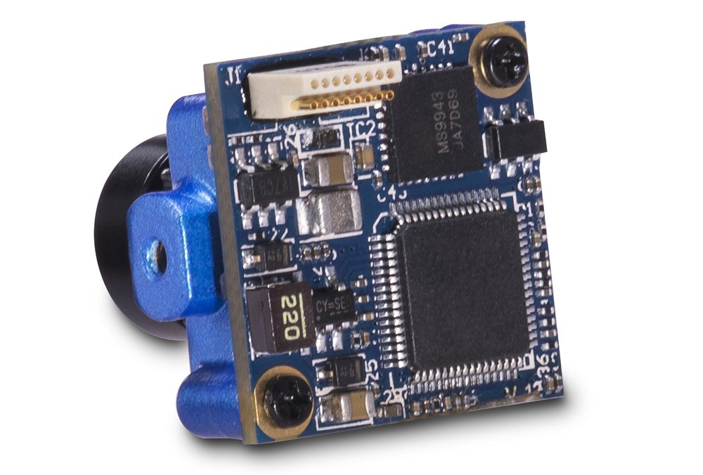
The shift from analog to digital electronics has brought new and improved capabilities in smaller package sizes. What once required a computer, camera, fax machine, and phone can now be done on a single device. To accomplish this pairing down of size and components, more electronic signals now fit into a reduced form factor. New chip and board materials have lowered operating voltages and current demands, thereby increasing battery life for portable devices. Those same processes and materials also brought a better understanding of impedance, and how something as seemingly simple as wire spacing inside a board or cable can have a dramatic effect on the quality of signals, especially those running at high speeds.
Additionally, to combat attenuation, connectors developed in the past two decades can push data and power using flat pins. Flat conductors have less field effect on neighboring conductors, improving signal integrity and performance. Follow that up with appropriate shielding around the exterior through use of conductive foil wrap or braid and it creates a compact solution that maintains performance across a wide array of environments.
From field radios to portable surveillance systems, each device is responsible for distributing power and signals accordingly. These devices include GPS and night vision devices, as well as Wi-Fi hotspots capable of transmitting real-time battlefield intelligence in some of the harshest environments on the planet.
Equipment used in the field has many specific considerations, such as damage resistance and environmental factors. Signal requirements are primary during the design process. Users want small lightweight solutions that deliver even in tough environments, and it is necessary to examine how every variable will affect size, weight, and power.
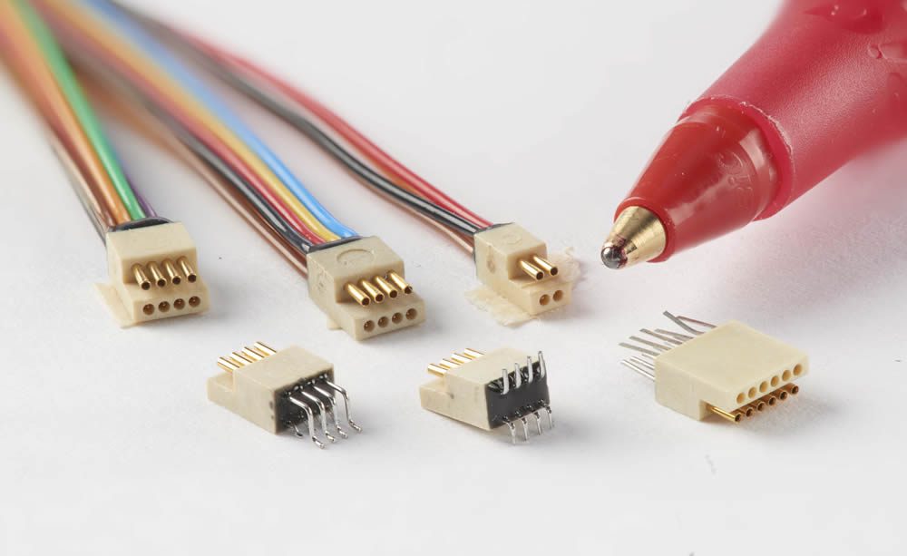
Omnetics’ PZN (Polarized Nano) ultra-miniature board-to-cable mounted connectors use the most rugged nano pin-to-socket systems to assure high performance in low-profile, lightweight interconnections.
Size
The size of connectors can be determined from customer preference, use case, or both. Connectors based on MIL-DTL-83513 and MIL-DTL-32139 specifications can be customized to different form factors that meet specialized requirements. Options exist to reduce the overall size of the connector, with one great option being hybrids. Hybrid connectors utilize several large contacts for power delivery with smaller contacts to carry signal and come in any number of form factors.
Hybrid circular connectors utilizing metal latches rather than traditional hardware are found in many high-reliability applications. For example, in a removable unmanned aerial vehicle (UAV) wing, hybrid circular connectors provide rapid field setup and power/signal delivery to vital components, such as servos and sensors. Their small size and circular shape pass through the wing spars without risk of getting caught or stuck in an unreachable location.
Hybrid circular connectors also appear in a multitude of soldier-worn applications. Chargers, tablets, radios, monitors, communication systems, and many other electronic devices promote health and safety and provide situational awareness. Hybrids provide data transfer through USB, Ethernet, or HDMI, while including additional power lines in packages smaller than the industry standard form factor.
Weight
Weight requirements are determined by application and environment; the latter plays a critical role in the end solution. While weight is a key requirement in soldier-worn applications, weight can have significant impact in equipment used in aeronautics, especially in space.
The introduction of cube satellites (CubeSats) in the late 1990s and early 2000s sparked a driving effort to reduce the overall size and weight of the craft while improving capability. Gone are the days of single, large, ultra-expensive satellites. Constellations of these nanosatellites that utilize small, ruggedized connectors are being launched regularly. Requirements for CubeSats may have a weight budget for plated plastic connectors only. Where EMI may be less of an obstacle, connector assemblies without metal housings keep the form factor to an absolute minimum. In other space applications, the need for an aluminum or stainless housing with gold plating is a necessity for shielding cosmic radiation.
SWaP has become a priority in many applications. In recent years, a number of connector manufacturers have started offering different form factors without a metal shell in alternate configurations to save size and weight while delivering much needed power. In these cases, weight is decreased by eliminating the metal housing, and using advanced polymers able to withstand the environment. Materials such as polyimide, PEEK, and Ultem, to name a few, are used in environments where resistance to chemicals and temperature is needed for extended exposure. Recent technology also allows for plating of plastics to enhance electrical properties, with overall weight of the connector being relatively unaffected by the addition of nickel plating.
More ruggedized lightweight connectors with metal shells are fabricated using aluminum alloys and plated for additional corrosion protection. This allows the protection and durability of metal without the risk associated with a “plastic” only connector.
Small lightweight ruggedized connectors have physics working to their advantage. Form factors, weight, and engineered materials combine to create solutions that are nearly insusceptible to damage from shock and vibration that occurs during launch.
Power
Power needs, followed by quantity of signals, are typically addressed first when designing miniature ruggedized connectors. Power should be considered in terms of voltage and current. In most cases digital signaling working voltage is low, and generally not an issue. Power demand may dictate a larger wire gauge than the 26 and 30AWG found in micro and nano-sized offerings. These deliver 3 A or 1 A of current respectively. Designers sticking with a traditional connector may end up spreading power across multiple contacts, which can ultimately affect the overall size and weight of the solution.
Mentioned earlier, hybrid solutions are an option for designers to provide specific power contacts and additional signal lines in a reduced size to keep the overall form factor at a minimum. Unmanned robotics and aerospace systems provide a great example of hybrid and SWaP in connectors. Power requirements have evolved from 30 A to over 300 A or more in heavy lift type applications over the past decade, with some adding signal to provide telemetry, pulse wave modulation (PWM), or other data transfer.
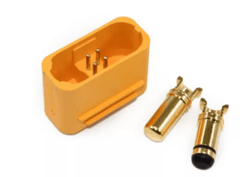
UAV power connector with additional signal pins
Voltage can also present challenges in terms of power and signal delivery and affect overall size and weight. Voltages above those found in the MIL-DTL-83513 or MIL-DTL-32139 base specification will require additional contact-to-contact spacing and insulation methods such as individually shielded contacts to prevent breakdown of the connectors. High voltage and current demands may create electrical noise inside the connector and require additional shielding. Shielding adds both size and weight to the overall solution through use of conductive braid, conductive shrink tubes, wraps, or ground terminations. In many cases, shielding is critical for maintaining device performance.
Fitting a factory’s worth of computing power into a package with reduced size and weight can be a real challenge. Solutions that fuse proven designs with alternate materials can be a great asset when it comes to reducing size, weight, and power demands. Designers open to use of materials outside of traditional specifications will find themselves with more solutions in their toolbox to address challenging environments.
Visit Omnetics Connector Corporation to learn more about high-reliability interconnects for next-generation military equipment.
Subscribe to our weekly e-newsletters, follow us on LinkedIn, Twitter, and Facebook, and check out our eBook archives for more applicable, expert-informed connectivity content.
- Maintaining Signal Integrity in the Era of SWaP - November 15, 2022
- Choosing the Right PCB Mounting Method for High Shock and Vibration - September 29, 2020
