Challenges of E-mobility Connectivity: Q&A
High power applications require innovative connectivity solutions that address battery performance, battery health, and safety.
We asked Shakib Shaikh, product marketing manager-North America, and Swapnil Bhale, lead engineer-new product development at Amphenol Communications Solutions, how connectors contribute to the performance, health, and safety of battery management systems (BMS) in e-mobility applications.
What do design engineers look for when selecting high power connectors in BMS applications?
When developing e-mobility connectivity solutions specifically related to the battery management system (BMS), the main concerns are meeting the mechanical and electrical constraints that are determined by the customer. The mechanical constraints refer to the space available on the board that determines the size of the connector. The electrical constraints refer to the voltage and current requirements. Sometimes there is also a thermal element, which goes hand-in-hand with the electrical and mechanical constraints.
What are the requirements for these connectors?
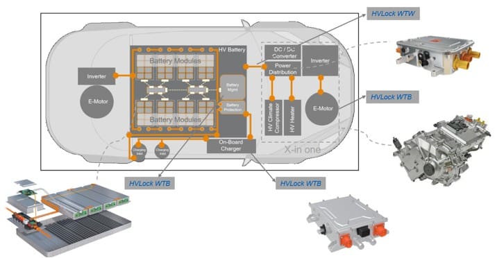
Within the BMS, we have requirements in three main areas. One is high voltage (800 volts+) and high current (20 amps+) applications, for example charging within the power distribution unit (PDU). The second is low current (1-5 amps) and low voltage (12V-48V) applications for monitoring. Examples of low power systems are headlights, wipers, interior lighting, volume controls, seat adjustments, and trunk release. Third is low voltage (approx. 100V) and high current (100-200 amps) applications. An example of this is the onboard charger that converts AC to DC power.
How does the system work?
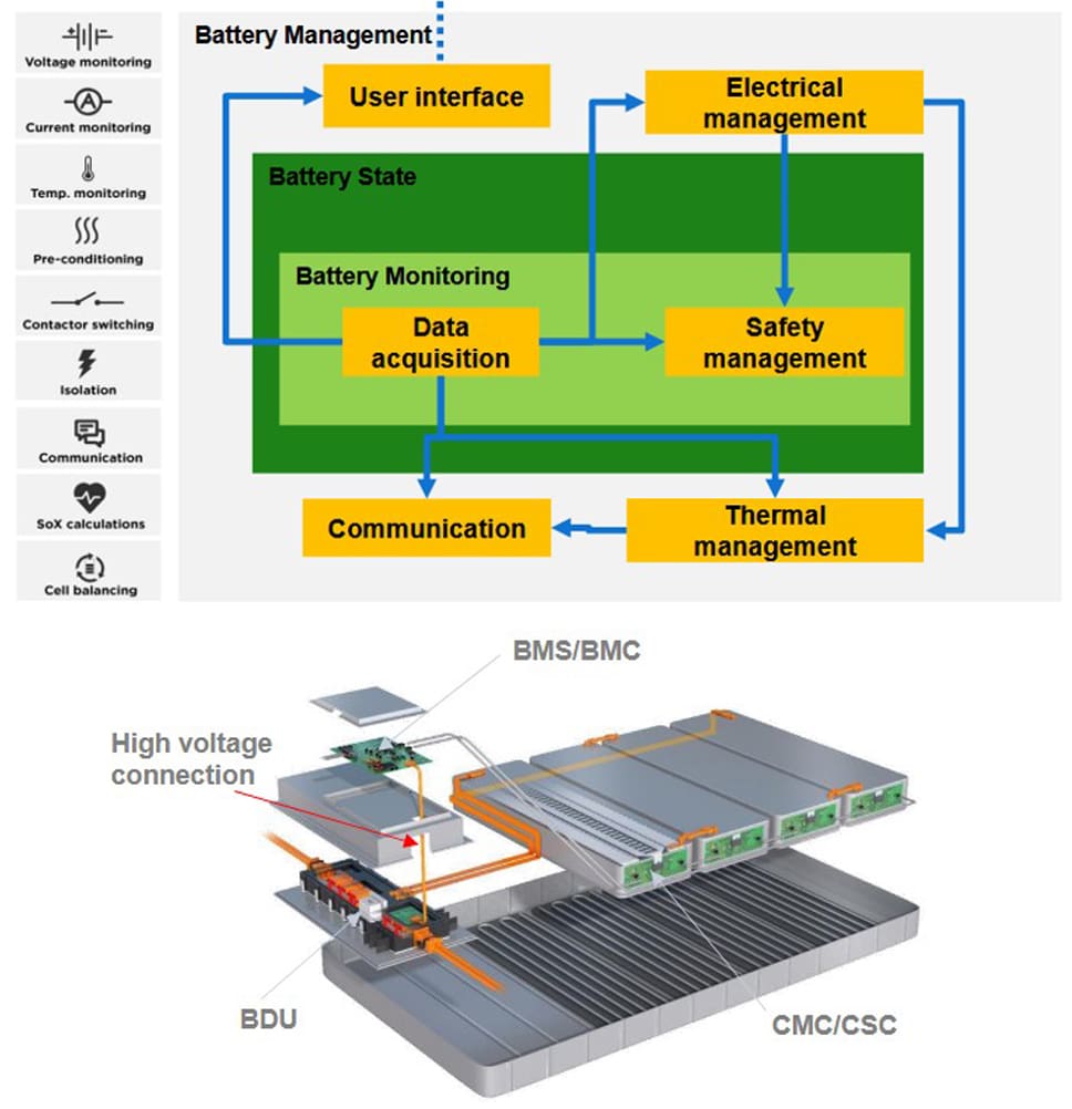
The battery management system tracks the status of each cell in the battery pack. An inverter converts the AC power coming from the grid into the DC power that the battery can use. Other systems convert high current/high voltage into low current/low voltage, or other combinations. All these systems have PCBs which require connectors. These connectors are not directly used for charging or powering but are used on a system that enables the charging or powering of the vehicle and the vehicle’s other electrical functions.
The BMS consistently tracks the charge and discharge activities of the battery pack and monitors cell voltages. Determining the state of charge (SOC) and state of health (SOH) helps estimate the amount of current needed for a safe charge and discharge operation without harming the battery. The data is useful in deciding if the battery is drained or sustaining passive cell balancing. Cell balancing is basically ensuring that all the cells, at least all the modules together, sustain the same voltage potential throughout the charging cycle. This helps maintain the overall health and performance of the battery.
What about safety?
The high-voltage conversions (AC to DC, DC to AC, DC to DC) are related to the safety of all the systems together. This includes passive safety or anything that directly impacts the driver or passengers. The high voltage area is responsible for several safety issues: total voltage detection of a single battery indicates the presence or absence of a voltage signal; insulation detection prevents thermal runaway and other safety hazards by identifying and isolating potential insulation faults; relay adhesion detection identifies when a high-voltage relay is stuck in a closed position, preventing it from properly switching off; and high voltage interlocking monitors the integrity of the high-voltage system to ensure that the high-voltage circuit is only energized when all components are properly connected and the system is in a safe state.
What is the main challenge in developing a high-voltage connector solution?
The main objective of a high-voltage connector system is to prevent arcing. As voltage increases, the risk of arcing also increases. The two metrics to consider are clearance (the shortest separation in the air between two conducting parts) and creepage (the shortest separation along the surface of an insulating material between two conducting parts). Connector manufacturers use specification IEC 606641 to determine creepage and clearance for a specific voltage.
A high-voltage connector system can be developed by increasing the pitch of existing products to create adequate space between the pins (clearance). However, this solution does not optimize size. As space continues to become more and more limited, new high voltage solutions are needed that fit in smaller connectors.
Using the principle of creepage, arcing can be prevented by placing a barrier (wall) between the pins. Instead of flowing from the top of one pin to the next, the fins cause the current to flow along the surface, up and over the wall. This creates a greater distance for the current to travel from pin to pin, thereby eliminating the risk of arcing without taking up more space.
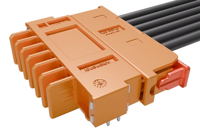
HVLock from Amphenol Communications Solutions uses fins to increase the distance the signal has to travel without increasing the space between the pins. This is an important consideration in e-mobility connectivity.
High-power connectors play a critical role in ensuring the performance, safety, and longevity of electric vehicles. With ongoing innovation, these systems will continue to advance the efficiency, reliability, and safety of electric vehicles.
Visit the Preferred Supplier page for Amphenol Communications Solutions to learn more about the company and its products.
Like this article? Check out our other articles on our Automotive Market Page, and 2024 and 2025 Article Archive.
Subscribe to our weekly e-newsletters, follow us on LinkedIn, Twitter, and Facebook, and check out our eBook archives for more applicable, expert-informed connectivity content.
- Three Companies, One Mission: Reduce Plastics in Electronic Connectors - July 28, 2026
- Cable Accessories and Tools Product Roundup - July 28, 2026
- Extreme Temperature Innovations for Aerospace and Defense - July 21, 2026