Best Practices and Solutions for Minimizing EMI
Mitigating the impact of electromagnetic interference begins at the board level when designing electronic systems for use in complex medical, aerospace, and other environments where multiple technologies operate.

Managing electromagnetic interference (EMI) is critical in busy settings where multiple and diverse types of electronic equipment are operating in tandem, such as medical, aerospace, military, and others. Excessive EMI can negatively impact the functionality of the equipment. Systems must be designed to protect equipment from EMI without impinging on the operation of other nearby electronics. However, if the correct process is followed, achieving electro-magnetic compatibility (EMC) can be straightforward.
Understanding EMI is a fundamental principle of electrical engineering: In an electrical circuit, electrons will always return to their source using whatever route is available. Correctly managing that return path leads to EMC.
Harwin’s EZi solutions focus on the board level to solve EMI problems.
Prevent accidental antennas
Metallic items such as wiring, PCB traces, and the leads on through-hole components can provide the means for either transmitting or receiving EMI. Whether intentionally or not, any two pieces of metal connected to a source can function as an antenna. Housing sensitive electronic circuitry in a metal enclosure can prevent the metals from picking up EMI from external sources. However, it is crucial that this is done correctly to prevent the metal enclosure itself from becoming an antenna. The enclosure must be properly connected to the same ground as the PCB via a number of low-impedance paths. One way to do this is to include metal pillars within the enclosure structure and ground-connected holes in the PCB. The enclosure is then attached by screwing the PCB onto the pillars. Although this will prevent EMI, it is not always practical since the labor and hardware costs can be high.
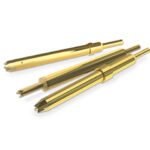
Using surface mount spring contacts
A more economical method is using spring contacts. These surface-mount components can be positioned on the PCB edge using pick-and-place machinery. They offer an effective ground connection once the board is pushed into place without costly amendments to the assembly process.
Harwin offers over 30 different spring contact variants complemented by 3D CAD models to assist with the design process.
Once the electronic system is shielded from external EMI and is not emitting EMI, the designer needs to address what is happening at the board level. Here, individual components or devices within the system risk interfering with one another. Analogue/mixed signal, RF, and digital devices can cause noise coupling when housing closely together. The EMI produced by a component which has capacitive or inductive properties can affect the signal passing through neighboring devices.
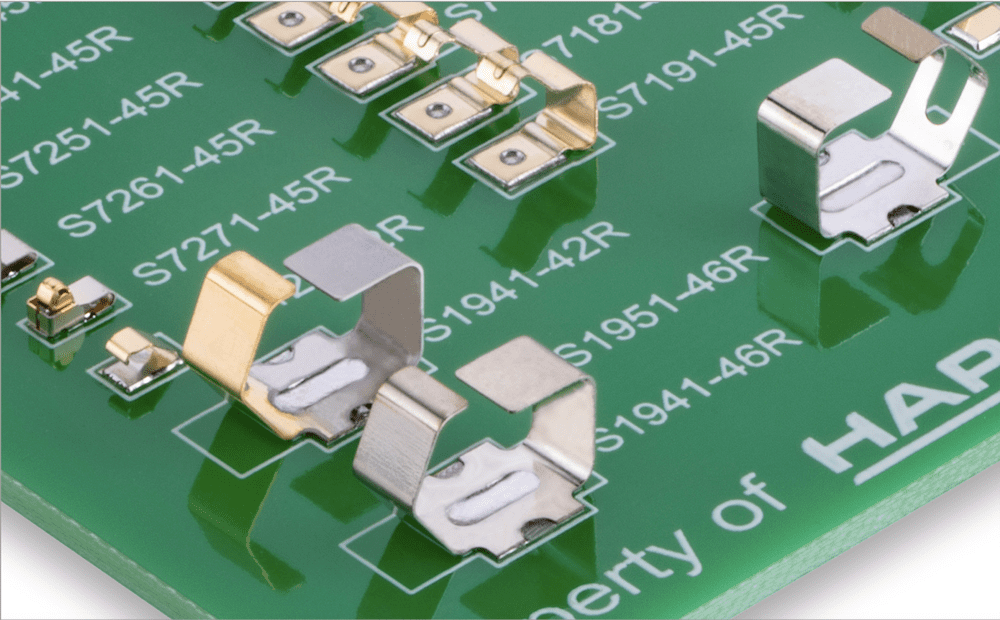
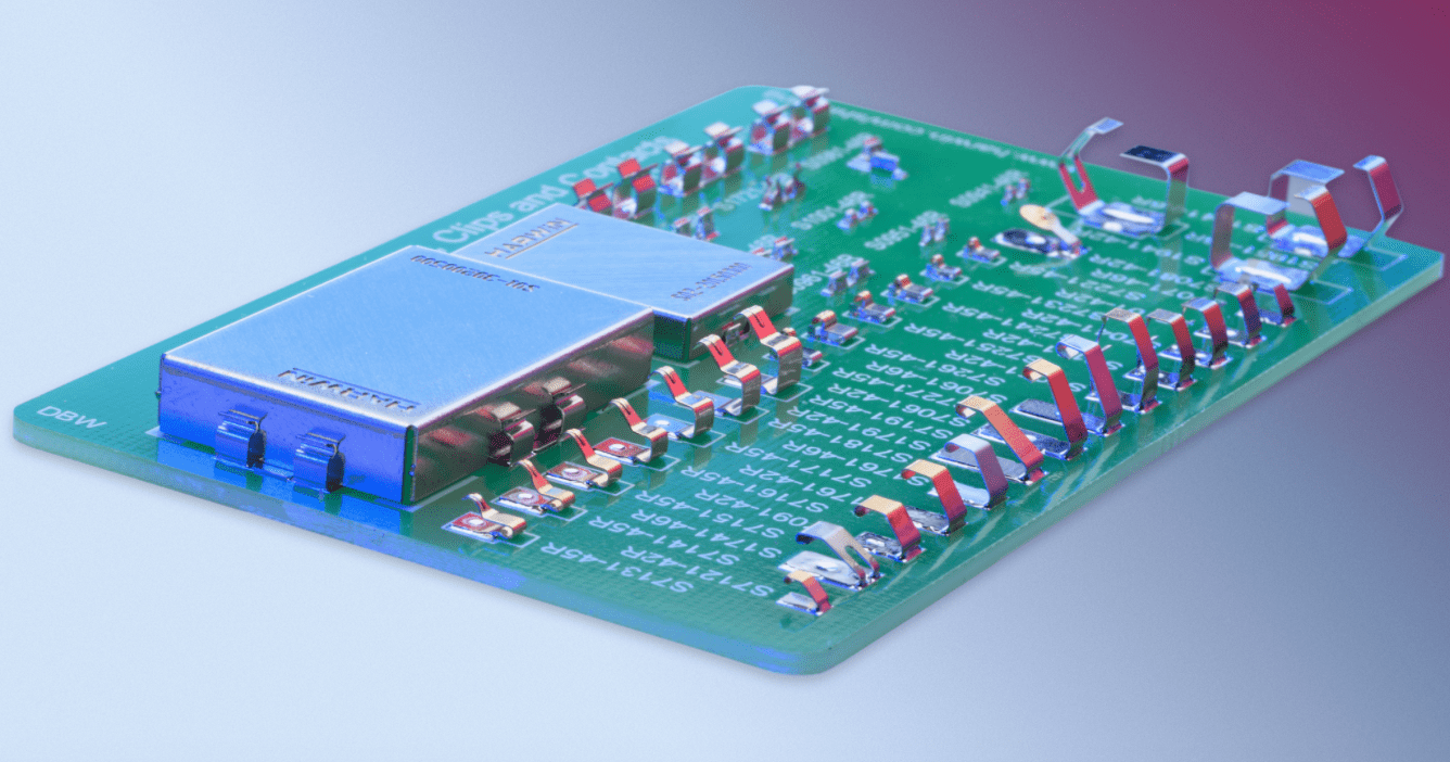
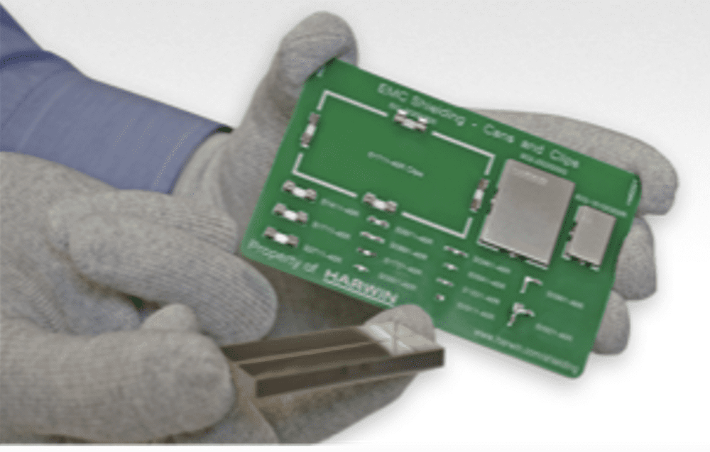
Board with spring contacts
Noise coupling can either be conducted (through PCB traces) or radiated (over the air). Radiated noise coupling can be addressed by putting metal covers (known as shield cans) over certain devices or areas of the circuit. Cans with through-hole terminations are readily available in standard shapes and sizes or can be made custom. Once the right can is found, the PCB must be designed with corresponding mounting holes, electrically connected to the ground plane.
By using a throughboard shielding can, you can add greater complexity to the assembly process. If all the other devices populating the PCB are surface mount, then soldering a through-hole shield requires a separate process, using either wave, selective, or hand soldering. This extra operation adds extra costs and may also create more EMI problems, as the through-hole terminations of the pin shield can also act as antennas.
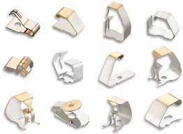
Surface mount clips offer a solution.
Surface mount clips can be used to hold metal shields onto your PCB. As there are no termination pins, this solution prevents the accidental creation of an antenna. The surface mount clips do not add an extra operation to your assembly, as they support automated pick-and-place operations.
Clips are available in different sizes and styles. Choose the level of retention force according to the application. If the metal shield needs to be removed for testing or debugging on a regular basis to access the circuitry inside, it is best to select clips with the lower retention force. For systems that are likely to be exposed to more extreme conditions involving heavy shocks and vibrational forces, the higher retention level is recommended.
Learn more about Harwin’s EMC solutions, including retention can kits, spring contacts, and RFI shield kits. See a video demonstration of EMI shielding strategies.
Like this article? Check out our other Connector Basics articles, our Medical Market Page, and our 2023 and 2022 Article Archive.
Subscribe to our weekly e-newsletters, follow us on LinkedIn, Twitter, and Facebook, and check out our eBook archives for more applicable, expert-informed connectivity content.