What are Precision RF Connectors?
Meet the Connector: Precision RF Connectors
Precision RF connectors are used to transmit an RF (radio frequency) signal from one point to another. They are typically used for higher frequencies in test and calibration applications that require high performance. Precision RF connectors are generally broken down into two key categories, instrument-grade connectors (IGC) and metrology-grade connectors (MGC).
The differences between precision and standard RF connectors are not detectable by sight, however precision RF connectors have a few significant distinctions.
Tolerances. Tolerances are determined by various standards for intermateability, but they are much tighter for precision RF connectors than for standard connectors. The interface tolerance for the pin to the reference plane of the connector, as well as for the dielectric, might be as little as flush to three-thousandths (0.003) in. below for a precision RF connector, compared to flush to ten-thousandths (0.010) in. below for a standard low-frequency SMA connector.
Materials. Precision RF connectors typically use passivated stainless steel or gold-plated beryllium copper instead of nickel-plated brass used on standard connectors. A standard dielectric in a typical connector is Teflon; a precision dielectric may use more exotic materials like PEEK, polyphenolic oxide, or Ultem (polyethermide).
Design. Going from one point to another often involves stepping up to a larger cable or down to a smaller cable or to a PCB. This creates line discontinuities that must be compensated for. These transitions are critical in precision RF connectors and the process to minimize them is far more complex than it is for standard connectors.
Cost. Precision RF connectors are typically much more expensive due to all the factors mentioned above – tighter tolerances, higher quality materials, and more precise design considerations.
High-frequency precision RF connectors are metric-based and are typically named for the number of millimeters that reference the inner diameter of the outer coax path (housing). This diameter, along with other dimensions, influences the connector’s frequency range, VSWR (voltage standard wave ratio) and other performance criteria, as well as its mechanical compatibility with other connectors.
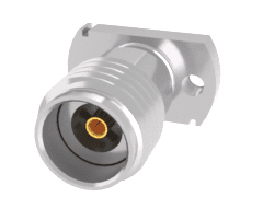
Samtec’s 50 Ohm SMA 2.92 Jack, vertical compression mount
3.5 mm and 2.92 mm connectors will mate with properly produced SMAs and with each other. The 3.5 mm was developed for use to 34 GHz. The 2.92 mm connector was developed for use to 40 GHz. Some suppliers offer an enhanced 2.92 mm for 44 GHz, but measurement may be uncertain as applicable calibration kits are only for a maximum frequency of 40 GHz. The male pin for 2.92 mm is designed to be shorter than that of an SMA or 3.5 mm. This is an improvement over SMA and 3.5 mm as this feature helps ensure that the outer housings engage before the pin and socket contacts, and helps prevent wear and mating stress that could result by misalignment in mating with SMA or 3.5 mm.
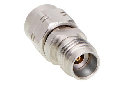
Molex 50 Ohms, precision test straight adapter 1.85 mm Plug-to-2.4 mm jack, passivated, 50 GHz
2.40 mm and 1.85 mm connectors are designed to intermate without damage. Although 2.40 mm are rated for 50 GHz, several top-level suppliers’ market them as substitutes for 1.85 mm for up to 55 and even 60 GHz based upon unique internal transmission design. (Consider a 1.85 mm with 2.40 mm interface.) Calibrations for 2.40 mm are done at 50 GHz and those for 1.85 mm usually are at 65 GHz. To help differentiate between the connectors, 2.40 mm plugs have notches across ridges in the coupling nut, while the 1.85 mm has an encircling groove in the coupling nut.
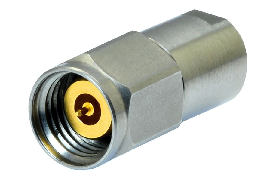
Radiall Sub miniature screw-on 2.40 mm precision connector, operating in the range DC-50 GHz
1.35 mm connectors (also called E connectors) were prompted by markets for millimeter wave sensors for self-driving vehicles, higher speed semiconductor/IC testing, along with expectations for to-be-defined industry applications and hardware to serve the relatively recent FCC re-defined E-Band. The 1.35 mm solved the problem of unintended unlocking of 1 mm connectors when performing time-consuming calibrations.
1 mm connectors are designed in for many test, wafer probe, and other applications for higher frequency requirements. Sourcing is limited by the extremely tight tolerances and micro-finish surface requirements necessary to produce these connectors, plus the need for testing by next-generation VNAs for DC to ≥ 110 GHz.
7 mm connectors, also known as APC-7 connectors, are an older precision connector originally developed by Hewlitt-Packard and later improved by Amphenol for performance up to 18 GHz. They have a low VSWR and feature a sexless coupling mechanism that permits any two 7mm connectors to mate. The connectors are relatively expensive and today usually are used for calibration and test in laboratory applications.
Design Notes
Standards: IEEE Std. 287.1-2021 defines precision RF connectors for test and calibration applications, including 3.5 mm, 2.92 mm, 2.40 mm, 1.85 mm, 1.35 mm, 1 mm, and 0.8 mm connectors.
Material specifications: Passivated steel or gold-plated beryllium copper for precision RF connectors. PEEK, polyphenolic oxide, Ultem, or other exotic materials for precision dielectrics.
Markets and Applications
Test & Measurement, Automotive, Industrial, Telecom/Datacom
Testing and calibration, higher speed semiconductor/IC testing, wafer probing
Suppliers
Precision RF connectors are available from many suppliers, including Hirose Electric, Molex, Radiall, Rosenberger, Samtec, SV Microwave, TE Connectivity, Winchester Interconnect
Like this article? Check out our other Meet the Connector and Connector Basics articles, our Transportation Market Page, and our 2024 and 2025 Article Archives.
Subscribe to our weekly e-newsletters, follow us on LinkedIn, Twitter, and Facebook, and check out our eBook archives for more applicable, expert-informed connectivity content.
- Bulgin’s Thisen Bird Becomes a Whitworth Scholar - June 30, 2026
- Board-to-Board Connectors Product Roundup 2026 - June 30, 2026
- COM-HPC 1.3 Takes Computing to the Intelligent Edge - June 23, 2026