Testing Integrated Circuits using High-Frequency Interconnect
When an interconnection network is inserted within a transmission line between an IC device and the attaching PCB, the connectors used must provide superior electrical performance while also meeting a range of mechanical requirements.
Integrated circuits have transformed electronic device design. Integrated circuits, also called ICs or semiconductor devices, have enabled designers to continually increase device performance relative to both speed and functionality. This evolution in system design has been accompanied by new package styles that fit higher I/O counts into smaller spaces and reduce interconnect feature size. However, these factors place considerable demands on the sockets and adapters used for interconnection.
An IC connector is an electromechanical device that provides a pluggable interface between an IC package and a system circuit board or subassembly. This interface must exert a minimal effect on signal integrity and be replicated as needed. Connectors enable the interface to be easily removed, providing ease of assembly, upgradeability, maintainability, and cost savings. Sockets enhance ease of maintenance, testing, replacement, or upgrades.
Understanding the scattering and reflection properties of traveling waves when an interconnection network is inserted within a transmission line between an IC device and the attaching PCB becomes increasingly important as devices reach GHz-level operating frequencies and beyond. S-parameter measurements in terms of reflection coefficients and transmission gain have typically been accomplished via the use of network and signal analyzers coupled with the use of special test fixtures and probing devices. Based on these measurements, network analysis provides the appropriate S-parameters from which impedance values may be derived and directly correlated via the use of Smith Charts.
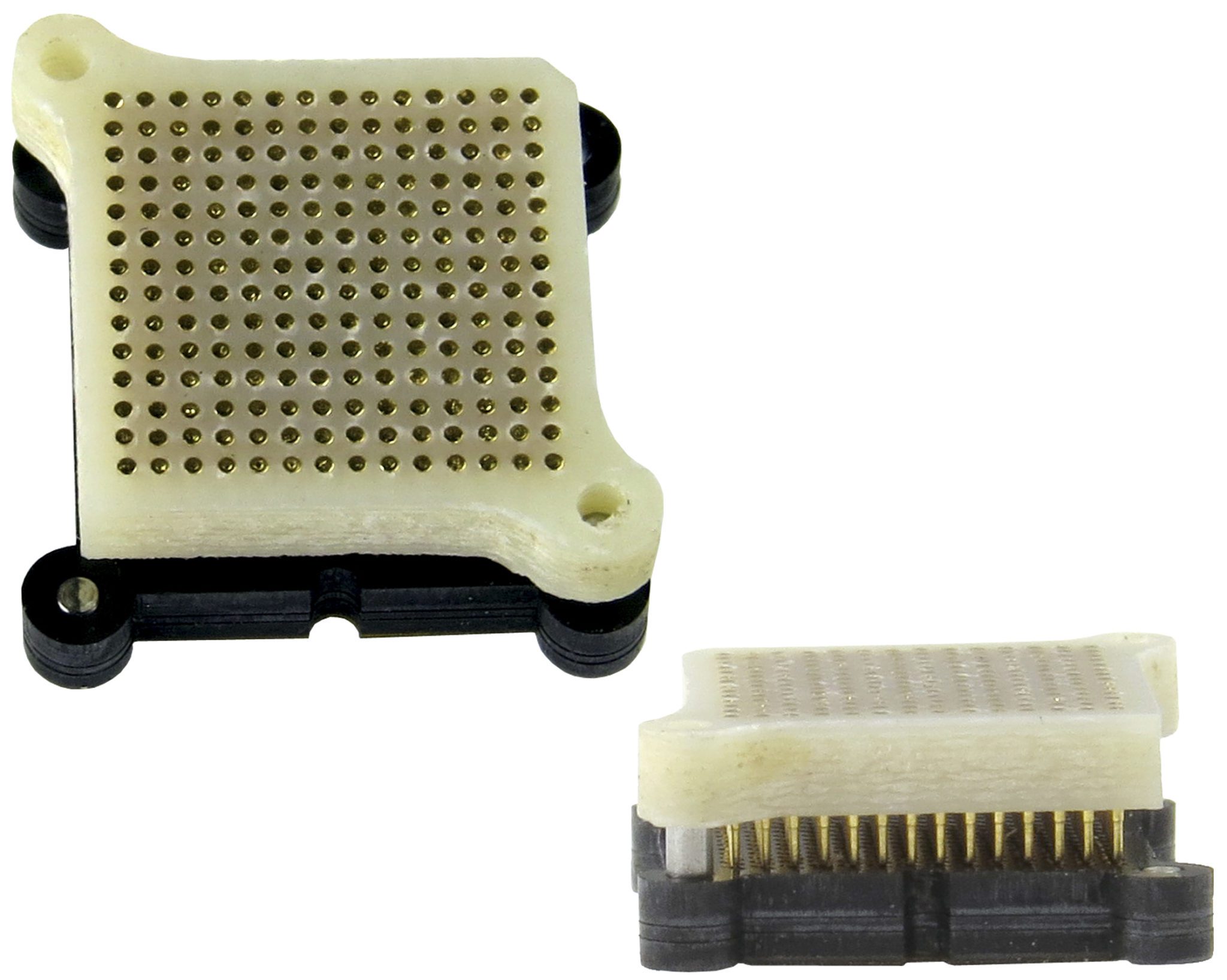
Figure 1: A custom 0.5mm pitch array connector by Ironwood Electronics.
For example, consider an oscillator. An oscillator always employs a sensitive amplifier whose output is fed back to the input in phase. Thus, the signal regenerates and sustains itself. The oscillator selected for a particular application should be capable of supplying an output signal whose upper and lower frequency limits exceed those required by the application. To verify the functionality of an oscillator, it is better to plug it into an application board using a connector, which eliminates the need for soldering and avoids damage to the oscillator. If the oscillator selected for the particular application is 20GHz, in order to verify 20GHz functionality, the chosen connector has to accommodate 20GHz frequency without significant loss.
Figure 1 shows a typical connector in array configuration. The connector pin is a single piece integrated clip design and is made of heat-treated Beryllium Copper Alloy 172 with 30 micro inch of gold over 100 micro inch of Nickel finish. The socket pin is press-fit into the polyimide substrate directly. RF performance of the connector can be verified using the below methodology.
For G-S-G configurations, a signal pin surrounded by grounded pins is selected for the signal transmission. For G-S-S-G configurations, two adjacent pins are used and all other pins are grounded. Measurements in both frequency and time domain form the basis for the evaluation. Parameters to be determined are pin capacitance and inductance of the signal pin, the mutual parameters, the propagation delay and the attenuation to 40 GHz.
Capacitance and inductance for the equivalent circuits were determined through a combination of measurements in time and frequency domain. Frequency domain measurements were acquired with a network analyzer (Agilent HP8722C). The instrument was calibrated up to the end of the 0.022″ diameter coax probes that are part of the test fixture. The device under test (DUT) was then mounted to the fixture and the response measured from one side of the contact array. When the DUT pins terminate in an open circuit, capacitance data can be collected. When the DUT pins terminate in short circuit, inductance data can be determined.
Testing was performed with a test setup that consists of a brass plate that contains the coaxial probes. The DUT is aligned and mounted to that plate. The opposite termination is also a metal plate with coaxial probes (actual device to be tested or a flat plate with embedded coaxial probes). Measurements are performed for a corner pin of the contact array, a pin at the perimeter (edge), and a pin in the center (field).
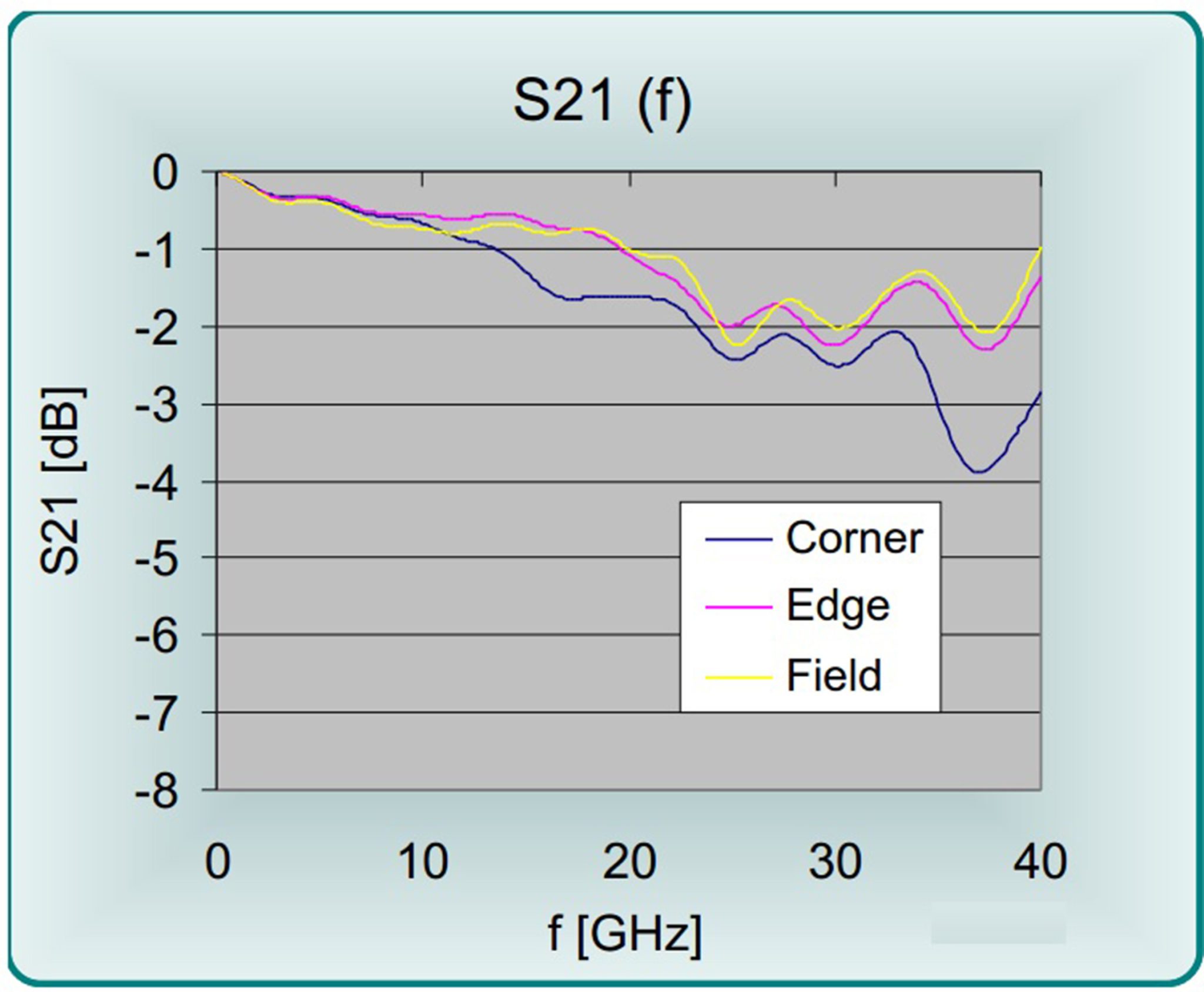
Figure 2: S-parameter data for corner, edge, and field array pins
An insertion loss measurement is shown in figure 2 for the frequency range of 50 MHz to 40 GHz. Insertion loss is less than 1 dB to about 13.5, 19.7, and 20.1 GHz (corner, edge, field). The 3 dB point is not reached before 35.1, >40 and >40 GHz. Insertion loss of -1dB @ 20GHz is interpreted as 90% of signal pass through the interconnect medium and only 10% of the signal is lost through the interconnect transition at 20GHz frequency. Note that only field array pins show -1dB@20GHz and the corner pins show [email protected]. This demonstrates that in addition to contact geometry, location of the contact pin plays a significant role in RF performance. This is critical for the test engineer, as the specific pin functionality in the DUT is being verified at the specific frequency.
Connectors used in high frequency devices must provide high electrical performance while also meeting a range of other mechanical requirements. The electrical path of the connector must provide high performance for the full physical length, from the top connection point to the solder tail on the bottom of the connector. The physical geometry helps determine its ability to perform at the specified frequency. The shortest connection length by far is within interconnect pin sockets, which provide better transmission of high frequency signals.
Like this article? Check out our other Connector Basics and high-reliability articles, our explore articles in our nine Markets, and our 2021 and 2020 Article Archives.
- Testing Integrated Circuits using High-Frequency Interconnect - August 3, 2021