A Step-by-Step Guide for Rugged Connector Selection
A Step-by-Step Guide for Rugged Connector Selection in the Era of Ever-Increasing Data Speed and Miniaturization Demands
By David Cianciolo, Engineering Director, Fischer Connectors, Inc.
Connector selection has morphed from the old standby, “How many contacts do you need?” into a much more serious challenge. Today’s design engineers need to find ways to pump increasing amounts of data through smaller and smaller spaces, and usability experts now add their ideas into the mix as well. This creates additional challenges, such as figuring out how to run both electrical and signal in a single connector and cable combination without interference, and alters the traditional, tried-and-true connector selection process.
Electrical Needs
Despite the changes that ever-increasing data speed and miniaturization demands have imposed on the rugged connector selection process, the first step hasn’t changed because physics hasn’t changed. Defining the electrical voltage and current requirements for each contact is still the first step to selecting ideal connectors for a given device. Specifying engineers have to ensure that they not only have the right number of contacts, but that the contacts can handle the power and signal demands of the application at hand. The size of the contacts and the size of the wire dictate the current-carrying capacity of a connector, while contact spacing, insulation materials, and the geometry of the insulator used to isolate the contacts dictates the voltage rating.
To ensure the design-in of the proper connector, engineers must dig into manufacturers’ test data to identify exactly how their testing was conducted and how their current rating and operating voltage specifications were derived, as testing criteria can vary.
When reviewing current ratings, it’s important to take note of the temperature rise specification, which indicates how much heat will be dissipated at a specific current value. It’s also important to confirm that the contact will support the selected conductor size, as a non-compatible conductor could cause overheating issues and lead to premature connector failure. (See Figure 1 and Table 1.)
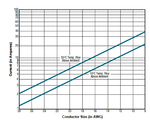
Figure 1: The relationship between current and conductor size.
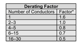
Table 1: *To identify the recommended current capacity, multiply the amperage value by this factor.
Additionally, it’s important to note that current ratings are intended as general guidelines for low-power electronic communications and control applications. Current ratings for power applications are generally set by regulatory agencies, including: UL, CSA, NEC, and others.
Data Speed
The focus on data speed has significantly increased over the past few years. Devices are now expected to transmit massive amounts of data to other devices connected by local area networks and the internet using specific protocols (e.g., USB 3.0, HDMI, or Ethernet). Additionally, when it comes to the critical applications that rugged connectors are typically employed in, the data transfer not only has to be accurate and without interference, but also has to be fast enough to trigger actions within fractions of seconds to ensure the safety of both people and equipment. As such, it is recommended that, when designing for data speed, specifying engineers engage in two rounds of design and testing — first via software and then by physically testing the chosen connector and cable combination.
Design Simulation and Testing
Designing a connectivity solution for a specific data protocol requires optimizing the design of both the connector and the cable, but the first condition for a functional solution is a connector that is capable of handling said protocol. Each protocol requires specific connector design rules, and multi-protocol connectors combine all of these specific rules. So, software simulation is the perfect tool for successfully navigating this design process, as it allows product engineers to verify the compatibility of their selected connector and cable assembly with the targeted protocol. Software simulation also allows the effects of design modifications to be immediately evaluated in both time and the frequency domain, enabling the achievement of optimized designs coupled with a high confidence level regarding the connector’s ability to perfectly match the desired protocols.
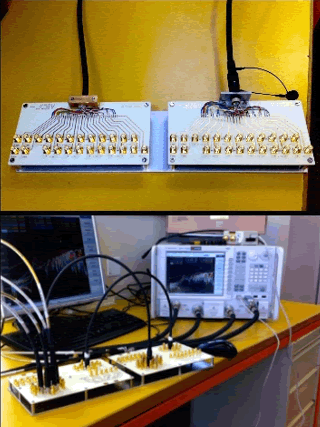
Figure 2: Characterization and qualification.
Once a design has been optimized for a defined protocol, a physical product prototype needs to be tested to validate the full characterization using a network analyzer. These devices measure and compare the S-parameters of a cable assembly with the target values defined in the protocol specification, and if one of the parameters falls, make an iteration loop on the design until the cable assembly fulfills all protocol requirements. At this time, the product can be declared protocol compatible.
The second condition for functional connectivity solutions compatible with specific data protocols is a cable that meets ISO/IEC 11801 specifications for general-purpose telecommunication cabling systems and delivers high performance as defined by parameters including: insertion loss (IL), return loss (RL), near-end crosstalk (NEXT), and far-end crosstalk (FEXT). Rugged interconnect solutions also often require cables that are capable of achieving certain speeds, such as USB 3.0 (5Gb/s). In these cases, it’s best to request specific cable recommendations from the connector supplier, as they have already gone through the trouble of multiple trial and error processes to identify the best cabling solutions for their connectors.
Terminations
Once the electrical and data transfer needs of rugged connector solutions have been addressed, and the foundation of the design has been simulated and tested, it’s time to select terminations. This is an important step because termination types have a direct effect on a connector’s assembly process and sealing capabilities. For instance, connectors with solder contacts are typically easier to seal against moisture ingress, while crimp contacts may offer better field reparability. However, there are several tradeoffs between the two, including: initial setup cost, suitability for low and high production levels, operator learning curve, heavy metals exposure, and process control. It’s also important to know exactly how and where the connector will be used and whether field reparability is a requirement, as these factors have a significant impact on the assembly equipment and manufacturing processes as well. So, specifying engineers should consult with their manufacturing and design groups before making a final decision regarding termination type to ensure that they’re making the best overall choice.
Sealing
The next step in the rugged connector selection process is evaluating the end-use environment of the connector. If the connector will be used in harsh operating environments, specifying engineers must check the ingress protection (IP) ratings of their options to ensure that their selection delivers proper sealing performance against dust and water ingress across various depths, conditions, and operating timeframes.
Most IP designations have specific conditions, but individual manufacturers can define the IP68 rating differently. So, when searching for a connector with an IP68 sealing rating, it’s critical to find out exactly how each manufacturer’s IP68 rating is measured. For example, a system submerged at 2 meters for 24 hours will have a different impact on the connector than a system submerged at 120 meters for 24 hours, but both situations can be defined with an IP68 rating.
Additionally, for vacuum and instrumentation applications, engineers may want to consider connectors sealed to even greater levels than are defined by traditional IP ratings: airtight hermetically sealed products.
Materials
Next, specifying engineers will need to address materials and reliability needs, noting that these decisions will directly impact how small of a connector they can ultimately select. Since these factors are inextricably intertwined — with smaller connectors requiring stronger materials to handle application requirements — some tradeoffs in terms of material selection and size may be required.
Selecting the right housing material is supremely important, as this factor impacts the reliability, weight, and cost of the overall connector. Brass connectors with nickel/chrome plating are traditionally more wear-resistant and have longer lifecycles than many other materials and, if weight is an issue, aluminum connectors are an attractive option. Brass and aluminum are the most preferred materials for miniature rugged connectors, and plastics are preferred for limited-reuse and disposable applications. Although, when considering plastic, it’s important to conduct adequate testing to confirm that the material will withstand the rigors of the end-use application and, when specifying plastic connectors for medical applications, to confirm that the connector can withstand any application-specific sterilization processes. Additionally, when specifying for aggressively corrosive environments, as well as some food industry applications, stainless steel may be required. Ultimately, though, the primary rule of materials selection is: Don’t sacrifice reliability for cost.
At this point, specifiers should also review the operating temperature range for the insulating materials used in the connectors they’re evaluating. This includes contact insulators, potting materials, and O-rings. Tables 2 and 3 can help with this selection process.

Table 2
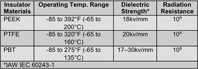
Table 3
Reliability Needs and Connector Characteristics
Once a connector’s electrical and data transfer design has been declared protocol compatible, and its termination, sealing, and material requirements have been addressed, it’s time to consider how frequently users will connect and disconnect the device over its lifetime. High mating cycle applications call for connectors with durability ratings in the 5,000 to 10,000+ cycle range. This selection is especially important if a failed electrical connection can put lives at risk, such as in medical or military environments, but may require tradeoffs with regard to miniaturization, as miniaturization often means fewer mating cycles.
Another requirement to consider is whether the connector will need to deliver consistent, stable performance in harsh and extreme environments. Connectors designed for indoor environments generally won’t deliver the same performance when exposed to extreme outdoor conditions. Table 4 contains information about various characteristics that should be taken into consideration when selecting rugged connectors for use in harsh environment applications.
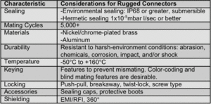
Table 4: Characteristics and considerations for rugged connectors employed in harsh-environment applications.
Miniaturization
All of the previous design selections will impact just how small the connector can be and what level of functionality one can expect from it. Currently, there is not a single industry that isn’t demanding that new equipment designs are smaller, lighter, and more functional, and frequently while remaining cost-effective as well. Connector design and selection should be addressed early in the product design process to take full advantage of the newest, smallest, and highest-functioning designs available on today’s market.
Great strides have been made with regard to miniaturization in recent years. Today, a single connector can solve connectivity challenges that would have required two or three connectors only a year ago — but it’s important to exercise caution. Specifying engineers should closely examine all aspects of each miniaturized connector, as the effects of these details become magnified as the voltage and current increases. To ensure suitable selections, compare models for pin size, number of pins, and functionality. Miniature connectors have compact packages that fit nicely in small places, but only a few can carry both power and signal. If the pin size is too small, it may not carry the amount of power required or its signal may be more susceptible to interference. Additionally, as connector packages get smaller so does their withstanding voltage. Miniature connectors are also extremely difficult to terminate, so miniature plugs and receptacles are often sold pre-wired to maintain reliability.
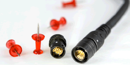
Figure 3: The Fischer MiniMax™ Series offers miniature connectors that combine signal and power while maintaining rugged characteristics.
Combining miniaturization and data speed is tricky, and only partially due to connector design. If a supplier claims that a connector can deliver data at a certain speed, always request test data and verify. Suppliers should be able provide evidence of achieving certain data speeds and supporting protocols such as USB, Ethernet, or HDMI, as well as to suggest appropriate cable designs or provide fully assembled connector and cable solutions. It’s also important to remember that the combined connector and cable solution must deliver the required speed for a miniaturized solution to make sense for an application. There have been all too many cases in which the cable and connector both passed independent speed tests, but did not work well when put together, which can both delay and add cost to design cycle.
Summary
Following the steps outlined in this rugged connector selection guide and involving suppliers and fellow designers in the selection process is sure to result in the design and specification of smaller, more functional, higher-performance, and higher-reliability devices. Although, there are still many details to address for each of these main bullet points, especially as all of the options surrounding cable assemblies and the realities of how data speed and miniaturization complicate connector selection begin to surface. Cable suppliers are beginning to address to the demand for increased data speeds, but selection is still limited and research into new cable solutions that will further enhance connector solutions is ongoing and continually resulting in new discoveries. Due to these many intricacies, rugged connectors are usually custom-built. There are some off-the-shelf options, but specifying engineers should be prepared for lead-times that are somewhat longer than those for commercial grade connectors. On the plus side, though, engineers specifying rugged connectors are likely to receive more personalized engineering assistance from companies that focus on rugged connector applications, which can help shorten both the learning curve and design cycle a bit.

Recently posted:
[related_posts limit=”10″]


