Range and Charge Time are Key in Battery Management System Design
Weight, vibration, and temperature are significant challenges in meeting the goals of long range and fast charging in electric vehicles and battery management system design.
Range and charge time are the main concerns of makers and buyers of electric vehicles (EVs) — how to go farther on a single charge and how to charge quickly. Weight, vibration, and temperature are significant challenges in meeting the goals of long range and fast charging that must be addressed in every aspect of the vehicle’s design and operation, including connectivity solutions. These issues, therefore, are top of mind when developing the interconnects used in a battery management system (BMS).
Battery Management System (BMS) Design
Vibration and temperature
Two organizations have established specifications for the automotive industry including for vibration and temperature. One is USCAR (United States Council for Automotive Research), a collaborative automotive technology company formed by three automobile manufacturers: Ford Motor Company, General Motors, and Stellantis. In Europe, the LV214 automotive standard was developed by representatives of German car manufacturers Audi AG, BMW AG, Daimler AG, Porsche AG, and Volkswagen AG. Both organizations rate the severity of vibration conditions from a range of 1, the most severe, to 5, the least severe.
In an EV, the most severe vibration (level 1) occurs near the tires. The passenger cabin experiences the least vibration (level 5). The BMS is located in the bottom center of the vehicle and falls somewhere in the middle of the vibration spectrum — a 2 or 3.
EVs are being designed to operate in temperatures from the extreme heat (think Dubai) to extreme cold (think northern Canada). The interconnects used must be able to withstand temperatures ranging from -40 °C to 130 °C, which includes temperatures in some of the harshest environments, said Shakib Shaikh, business development manager, Amphenol Communications Solutions.
BMS architecture addresses vibration, temperature, and weight
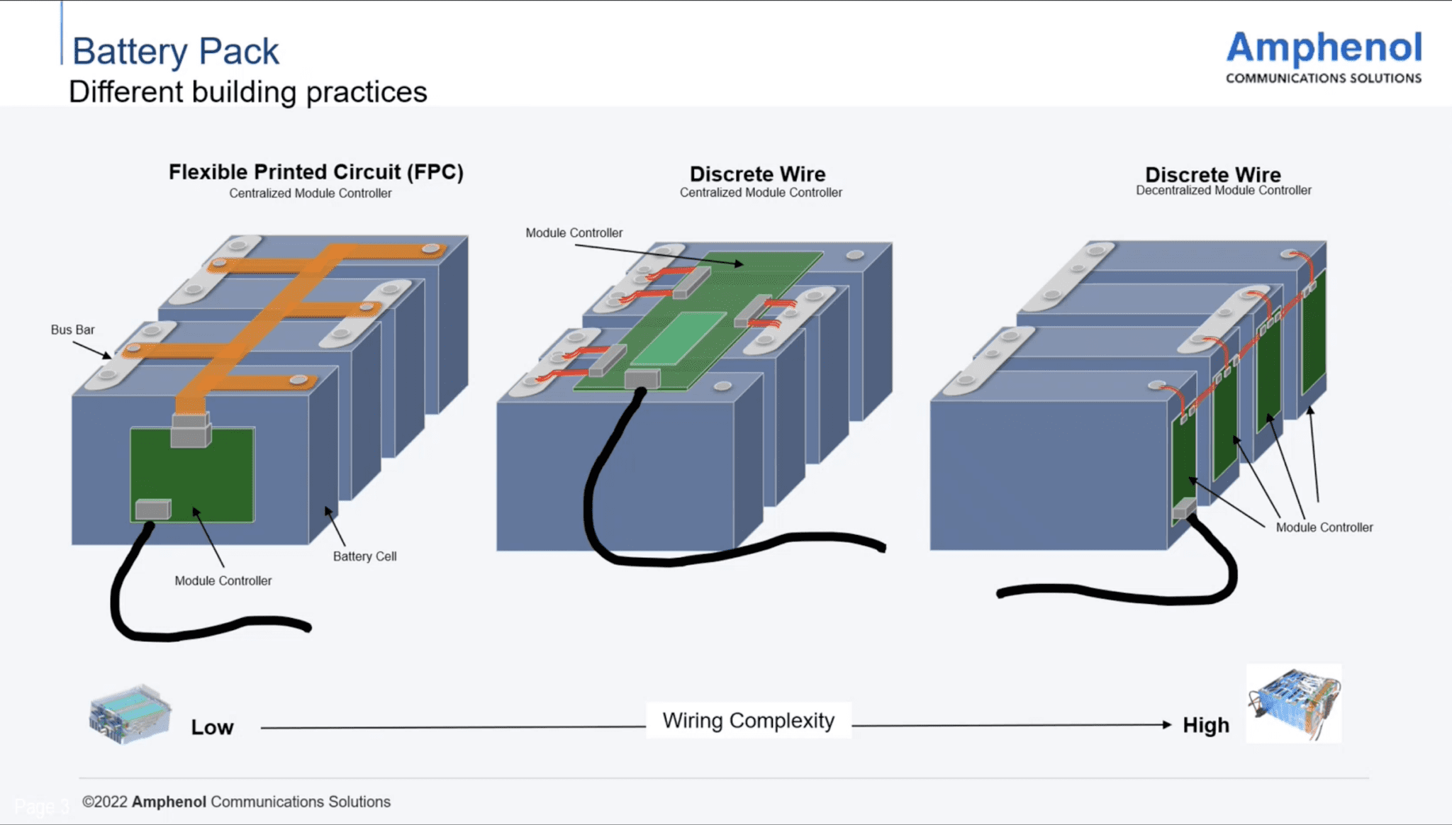
Figure 1 Different battery pack arrangements used for BMS
Multiple methodologies and architectures are used for BMS. Figure 1 illustrates how signals are routed. Each of the blue boxes represents a cell and the cells are connected to form a battery pack. Inside each cell is a monitoring function that determines its health, charge levels, performance, and heating. Also in each cell is a conductivity element that determines how each of the cells is doing. This is commonly accomplished using a wire type architecture, but flex circuits are gaining popularity.
“We’ve seen a migration to flex-based architecture, which has pros and cons,” said Shaikh. The biggest benefits of a flex-based solution are that it is extremely lightweight and very easy to bend. A sharp bend radius will be very difficult for a cable, especially one with larger pin counts, to accommodate, and cable is much heavier than flex. Flex is a great option to reduce weight and save space, however it is typically more expensive, Shaikh explained.
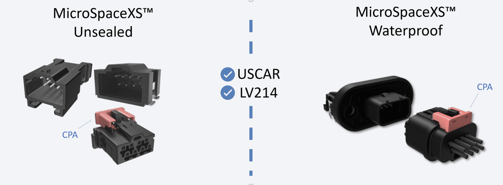
Amphenol’s Minitek MicroSpace™ connector platform’s unique design enables LV214 Severity-2 that makes this crimp-to-wire connector especially suitable for automotive applications. Its vibration-tolerance is marked by its high connector locking strength of more than 75N.
Vibration can compromise the connections. A loose connector in a BMS can cause the vehicle to stop moving and potentially cause a catastrophic situation. MicroSpace from Amphenol is a lightweight connectivity solution that addresses the USCAR and LV214 requirements for level 2 resistance to vibration and withstands extreme temperatures.
According to LV214, the audible click occurs when the receptacle is mated with the header, providing notification that the mating has been completed. If the operator doesn’t hear the click, however, there might be a risk of a bad connection. MicroSpace, therefore, has the CPA (connector position assurance) in the form of a red tab (red indicates it is a security part). When activating the CPA, it will shift underneath the latch if the mating is fully completed. If it was not fully completed, the CPA cannot be activated and the operator is informed something has gone wrong.
When the CPA is activated, it also ensures that there is no accidental unlatching. The force to engage and disengage the CPA is described in the USCAR and the LV214 specifications. “The click basically gives the operator a notification that the connectors have mated and that the secondary lock is activated,” said Shaikh.
An additional feature, which is an automotive requirement, is terminal position assurance (TPA). Each terminal has a primary latch. The force to insert the terminal into its final position cannot be so high that it creates buckling of the cable, but this results in a lower, weak retention force of the terminal in the housing. When assembling a cable harness in a car there might be unintentional forces applied on cables that arrive at a terminal. As the primary latch of the terminal might not be strong enough to ensure the correct position in the connector while the harness is being pulled, it is important to keep the wiping length stable to have a guaranteed electrical connection. The TPA has two functions. First, it visibly shows that something is wrong if after inserting the terminal, the TPA cannot be activated completely. Second, when the TPA is inserted, it gives additional retention force to the connector.
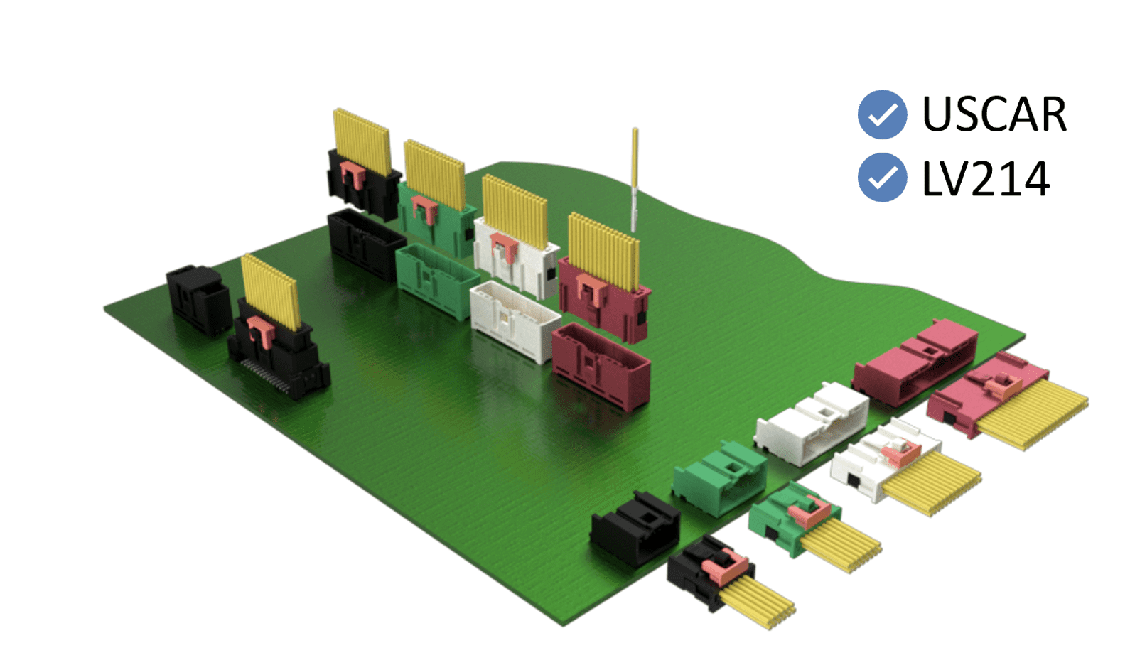
WireLock® is a 1.80mm pitch wire-to-board connector system from Amphenol. Its compact design addresses the growing need for space-saving automotive-grade connectors.
Amphenol Wirelock is suitable for larger pin count applications. MicroSpace accepts up to 30 signals, while Wirelock accepts up to 40 signals and is slightly larger. Aside from that, they are identical in performance, in current carrying capability, and in terms of automotive requirements.
“BMS applications typically require three to four amps, however, we are seeing applications pushing the limit, and they need a little bit of headroom,” said Shaikh. “We’ve taken the same access and created a derivative that still maintains all the other design features, such as the shape and the geometry, but reaches six amps per pin, which gives a little bit of breathing room in some applications.” Automakers are pushing the threshold to reduce the amount of time needed to charge a vehicle, which requires pumping higher voltage through the vehicle.
To avoid arcing between contacts at high voltages, the contacts need to be properly spaced. The higher the voltage, the more space is needed for clearance (the shortest separation in the air between two conducting parts) and creepage (the shortest separation along the surface of an insulating material between two conducting parts). Naturally, greater distance between contacts increases the size of the connector. This impacts the connectors in the BMS and those in the charger. To optimize the lifetime and efficiency of the battery, the BMS needs to control the current during charging and discharging phases and may need a high voltage connector interface for measurement of the current.
Minitek MicroSpace™ high voltage solution with de-population contacts
Altitude also impacts creepage and clearance. Air acts as an insulator, and since there is less air at higher altitudes, the contacts need to be farther apart. Amphenol has come up with a solution that allows OEMs to push the charge time and respects the creepage and clearance required at 3000 V. In addition to accommodating higher voltage, this not-yet-released solution accounts for the reduced air at higher altitudes.
What else is new?
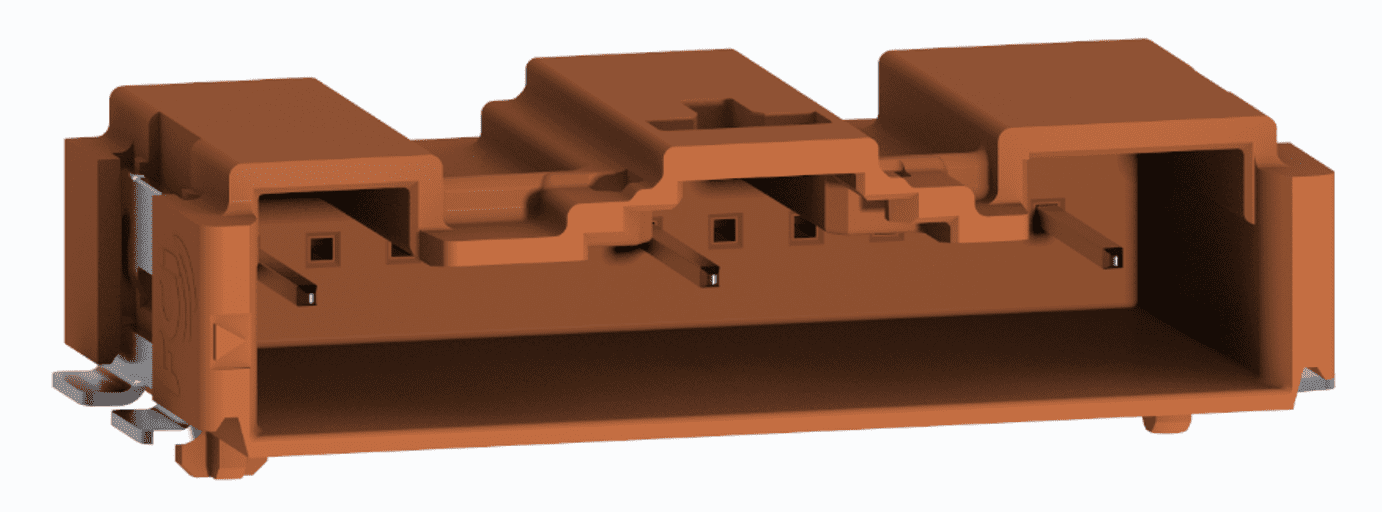
Another trend is around flexible connector design. “We are seeing applications where the customer wants to have wires or flex coming into this connector,” Shaikh said. The idea is that designers would start off with wires and once the design is finalized and the production is mature, they would transition over to a flex. This requires a universal header, which can accept a cable and a flex. Amphenol’s solution is FlexLock. The board side is fixed, and the receptacle side changes from wire to flex, and vice versa, at any point in the design cycle.
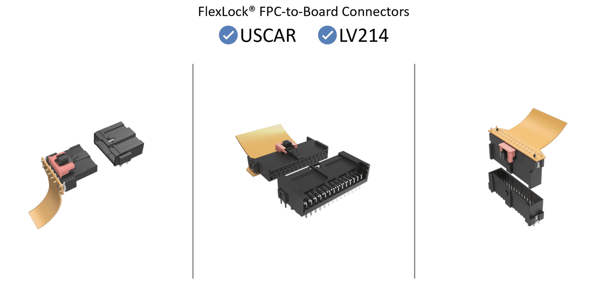
FlexLock® FPC-to-Board connectors from Amphenol have a compact design that is compliant to USCAR-T2V2 and LV-214 S3 specifications.
Because the flex is so thin customers are starting to request a low-profile header. “We’re in the process of reducing the height of our standard Flexlock by about 30-40% because for some BMS applications height is a concern. It’s not available yet, but we have a low-profile Flexlock in the works,” said Shaikh.
To learn more visit Amphenol Communications Solutions Preferred Supplier page.
Like this article? Check out our other articles on Wire & Cable, EVs & HEVs, our Automotive Market Page, and our 2022 Article Archive.
Subscribe to our weekly e-newsletters, follow us on LinkedIn, Twitter, and Facebook, and check out our eBook archives for more applicable, expert-informed connectivity content.
- Extreme Temperature Innovations for Aerospace and Defense - July 21, 2026
- Connectors for Soldier Systems Product Roundup - July 21, 2026
- July 2026 Connector Industry News - July 21, 2026
