Improving Signal Integrity Performance in Micro-Coax Cable Assemblies
Can signal integrity (SI) performance be improved by using a connector with a paddle card?
In a test case, a paddle card with high SI performance is combined with a low connector height to achieve an ideal solution.
Infrastructure telecommunications equipment, such as servers and switches, has become increasingly faster for enterprise computing environments. Therefore, signal integrity (SI) performance must be improved for each component used in these systems and has a role in ensuring equipment performance. The challenge is that conventional printed circuit board (PCB) trace transmission has large insertion losses with limited transmission distance.
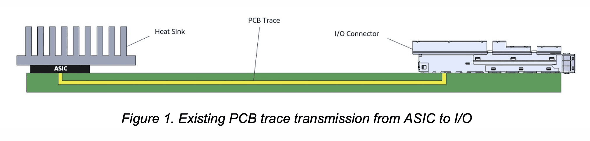
The premise is that the transmission loss must be improved while lowering the connector height. The reason for this is the connector may need to be placed under the heat sink (as shown in Fig. 2) to bring it closer to the ASIC (application-specific integrated circuit) to reduce PCB transmission loss. (Transmission speed is assumed to be 64 Gb/s PAM4 [frequency 16 GHz].)
Figure 1 below shows the conventional PCB trace transmission from ASIC to I/O.
Existing micro-coaxial connector products have no transmission quality problems up to about 13 GHz. However, resonance occurs around the target frequency of 17 GHz, resulting in deteriorated transmission quality.
Graphs 1 and 2 below show near-end crosstalk (NEXT) and far-end crosstalk (FEXT) for conventional products. The red circles indicate resonance points.
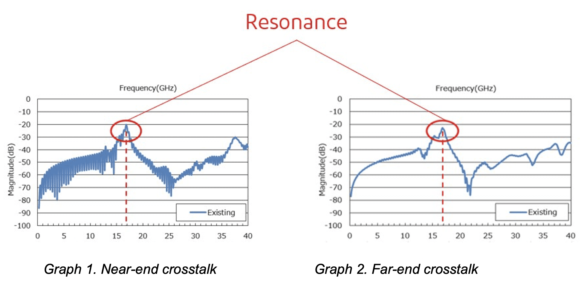
The resonance frequency that occurs is dependent on the length of the ground return path. If the length of the ground return path (wavelength “λ” ) is long, the resonance frequency occurs in the low frequency band. Conversely, if the length of the ground return path is short, the resonance frequency occurs in the high frequency band.
Jumper harnesses that use cables to address the main challenges are attracting attention as a possible solution. Figure 2 shows the jumper harness transmission from ASIC to I/O, instead of PCB traces as in Figure 1 above. This solution can reduce transmission loss by minimizing the PCB trace length using a low-profile connector, which can be placed under the heat sink (closer to ASIC), and with a directly terminated cable to an I/O connector.
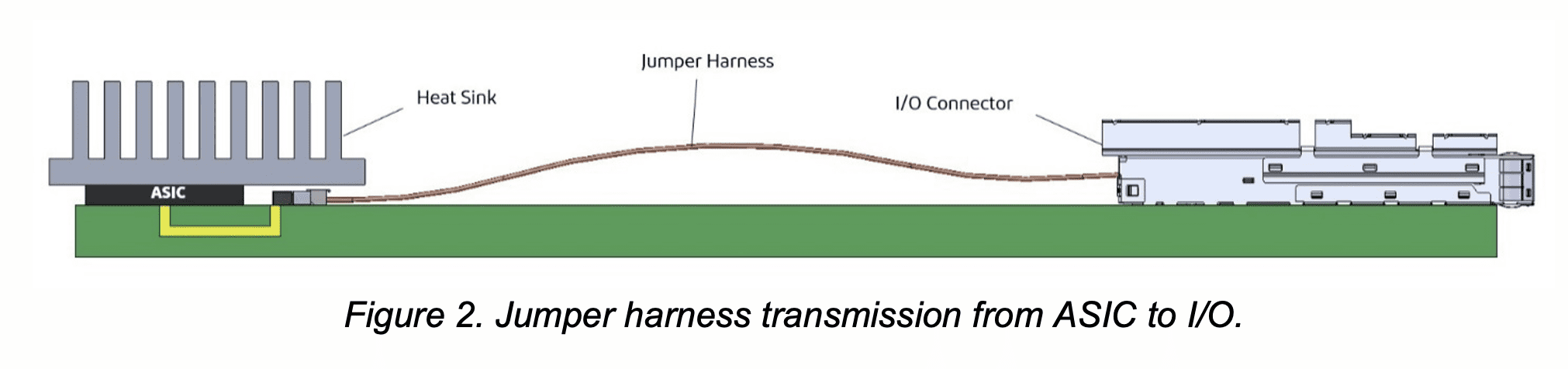
Figure 3 below shows the structure of the mating condition of the plug and receptacle of conventional micro-coaxial connector products. Due to the structure of the connector, the ground path cannot be easily set. Cable and terminal ground paths are connected by ground fingers.
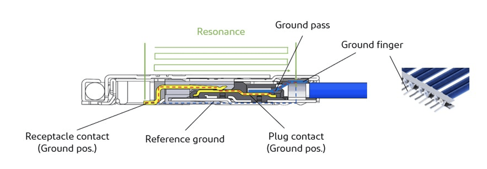
Figure 3. Cross-section of connector without paddle card. (The area in green indicates the resonance area.)
By replacing the existing plug connector with a paddle card, the length of the ground path can be shortened. This pushes the resonance out to a higher frequency.
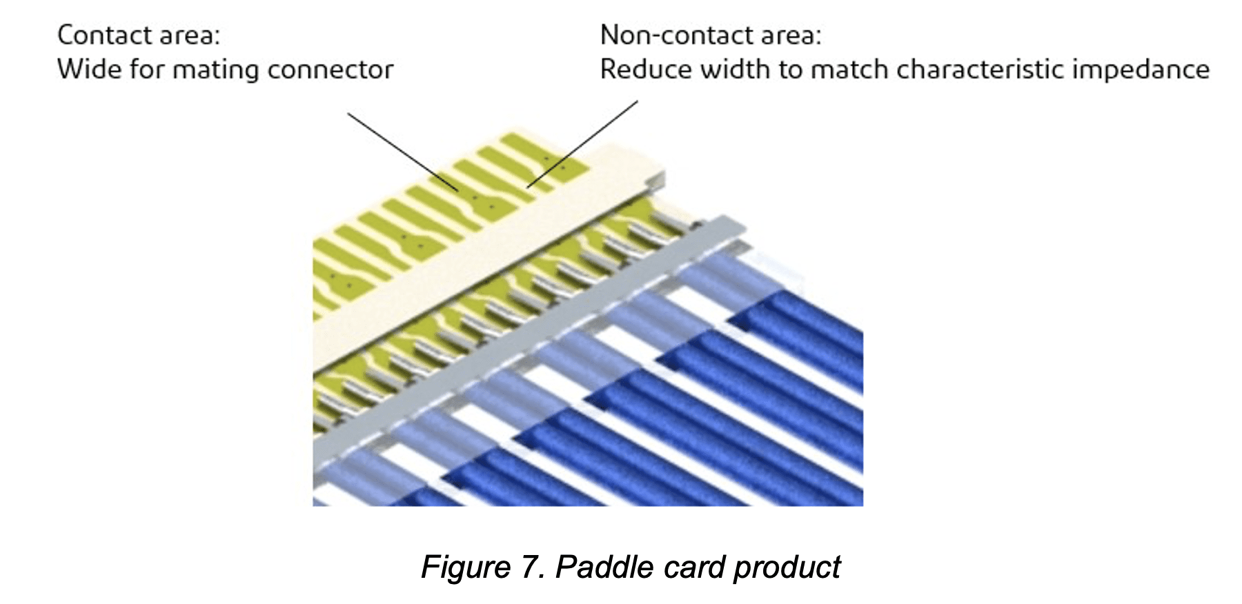
What is a paddle card?
Paddle cards are PCBs or flexible printed circuits (FPCs) to which cables can terminate, allowing the addition of multiple ground return paths. Using paddle cards, impedance matching is simplified, and signal integrity is improved at higher frequencies.
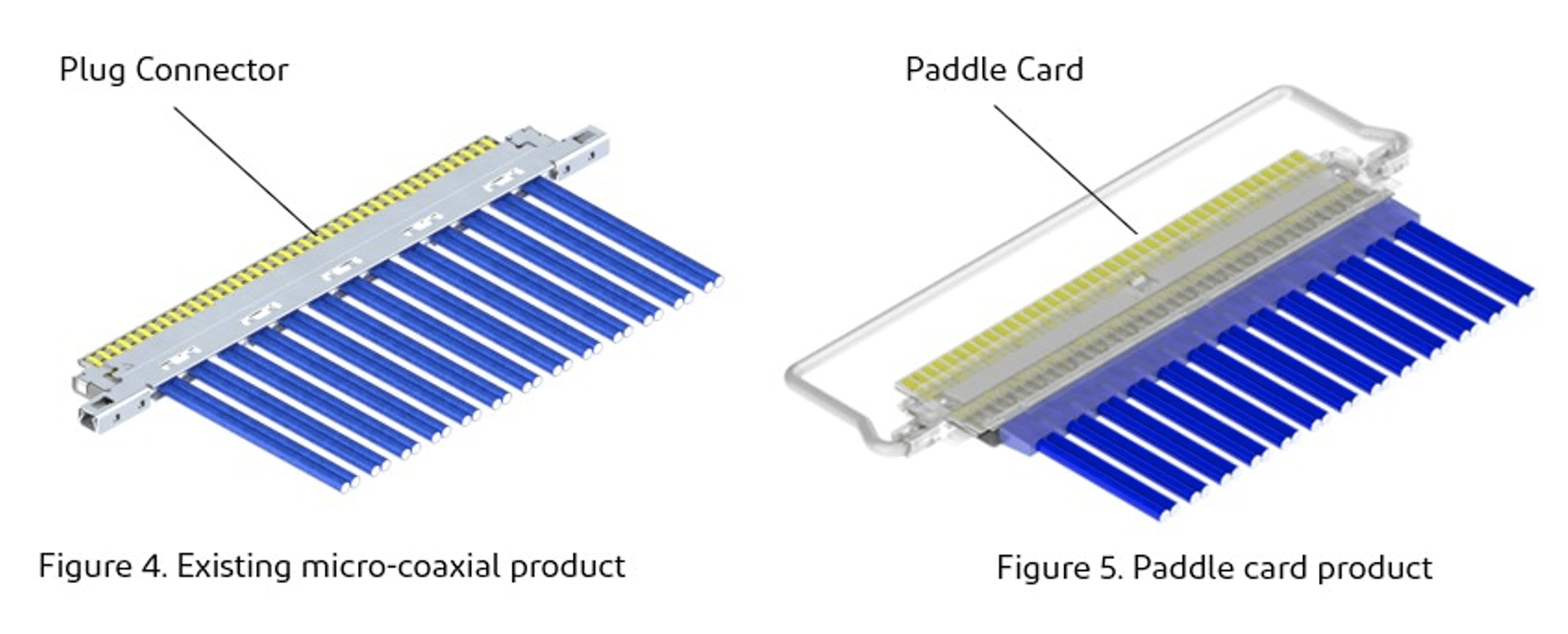
Figure 4 below shows the appearance of a conventional micro-coaxial harness. Figure 5 shows the appearance of a micro-coaxial harness with a paddle card. Mating contacts (pads) are configured on the paddle card.
Below, Figure 6 shows the structure of the mating condition of the plug and receptacle of a connector with a paddle card. It is possible to set up many ground paths through the paddle card allowing greater design flexibility.
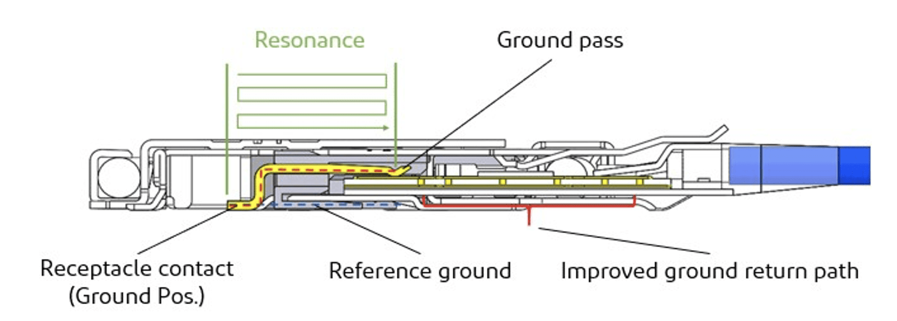
Figure 6. Cross-section of paddle card product. (The area in green indicates the resonance area.)
By using a paddle card, the signal line width can be adjusted to specific requirements and the characteristic impedance can easily be matched.
Figure 7 shows a micro-coaxial cable that is assembly soldered to a paddle card. The width of the paddle card contact pads must be sufficient for mating the contact with the receptacle. The pads can be narrower at non-contact areas to optimize the characteristic impedance.
Test results
Simulation setup using analytical software Ansys HFSS 19.0:
- Frequency: 0-40 GHz
- Cable: Micro-coaxial cable, AWG #36, 42.5-ohm
- Cable length: 254 mm (10 inches)
- Connector on both ends
- Pin assignment: GSSGSSGSSG (G: Ground, S: Signal)
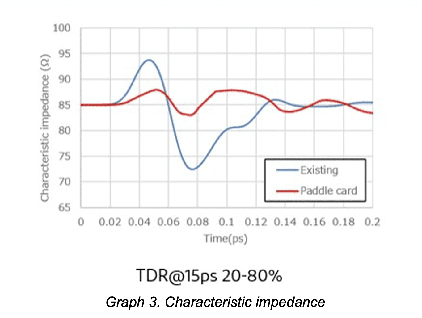
Improved characteristic impedance
The existing product had a characteristic impedance ranging from 73-94 ohms. However, the paddle card product had an improved impedance range from 84-93 ohms. Graph 3 below shows that comparison.
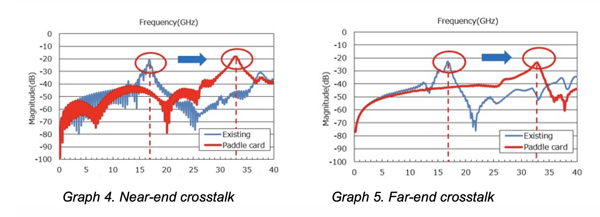
Improved NEXT and FEXT
Paddle card products can shift the resonance frequency. As shown in the graphs below, the resonance frequency has been shifted from 17 GHz to 33 GHz. Thus, transmission up to the 25 GHz band is now possible.
Graphs 4 and 5 show results for NEXT and FEXT. These are comparisons between the micro-coax connector without a paddle card and an improved product with a paddle card. The red circles indicate the resonance points.
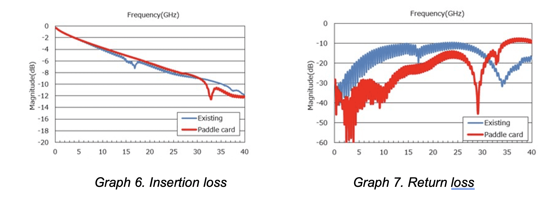
Improved insertion loss and return loss
Insertion loss and return loss also improved by improving the characteristic impedance. Graphs 6 and 7 show results for insertion loss and return loss. These are comparisons between the existing product and the improved product with a paddle card.
Summary
The test results confirm that SI performance has been improved by using a connector with a paddle card. In a layout where internal space is limited, such as servers and switches, a paddle card with high SI performance combined with a low connector height is an ideal solution.
Learn more about I-PEX’s CABLINE-CAP solutions.
Like this article? Check out our other articles on Cable, Cable Assemblies, our Wire and Cable Assemblies Market Page, and our 2023 Article Archive.
Subscribe to our weekly e-newsletters, follow us on LinkedIn, Twitter, and Facebook, and check out our eBook archives for more applicable, expert-informed connectivity content.